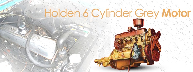
Holden gained engine building experience during WW2, when it manufactured both aeroplane, boat and torpedo engines for the war effort. The Grey six (so named because the entire long motor was finished in a "grey" paint) was born with its success to be seen as a measure of GM-H's new car.
Holden wisely choose reliability over innovation, durability over performance. The 6-cylinder design was chosen as a compromise between the British cars, with their sometimes unreliable 4-cylinder engines, and the larger US cars that featured more expensive to manufacture, maintain and run V8 engines.
It was a square engine, featuring a four-bearing crankshaft, gear-driven camshaft and full pressure lubrication system with provision for accessory oil filter. It had a capacity of 132.5 ci (2.15 litres), a compression ratio of 6.8 and developed 60bhp (rated at 21.6hp).
The fuel system used a cam driven mechanical fuel pump feeding a single-barrel, manual choke downdraft Stromberg carburettor. An oil bath air cleaner was an optional accessory. Delco Remy electrics (starter, generator, distributor etc.) were used on early engines until Bosch units were phased in early 1953.
The torquey, low stress unit was extremely flexible, economical and offered at the time lively acceleration. An added benefit was that it was easy to work on. With its success through the '50s and early 1960's the grey engine was carried over into each new model series with only minor modifications - new camshaft, higher compression ratio, incorporation of larger valves and throat surgery in the form of improved carburettors. By the time the FB was released the capacity was up to 138ci (2.26 litres) with a compression ratio of 7.25 and an output of 75bhp (56 kW). If you are trying to identify if the grey engine fitted to your Holden is original, the following engine number sequences may help:
- 48-215 numbers started at 1001
- FJ numbers at 121694
- FE numbers at L283373
- FC numbers at L439507
- FB numbers at B1001
- EK numbers at B175814
- EJ numbers at J1001
The First “Hot” Holden
Not long after the first Holden rolled off the assembly line, there were young rev-heads looking to tune the grey engine in an attempt to extract better performance. At first 100 bhp was considered a respectable goal for an iron headed Holden, by
1960 that figure had jumped to around 135 bhp, and by the end of production it was closer to 150 bhp. We have been told that modifiers who took the alternative route of fitting special
cylinder heads to the basic block assembly were rewarded with over 200 bhp.
Among the first Aussie race pioneers to see the Holden’s potential were the likes of Jack Myers, Dick Shaw, Charlie Dean and Tom Geoghegan. With the true potential uncovered, Holden dominated sedan car racing until the advent of the 3.4 Jaguar. This was not the only sphere where Holden was setting the pace. What may have been the very first hot Holden was built up by Sydney tuner Merv Wargott in 1949, this iteration being installed in a speedboat – and during the 1950s the “grey” was a popular choice for aquatic propulsion. The engine also made its presence felt in speedway racing. By 1956 almost every enthusiast knew that 100 mph had been shattered with a 105 mph run by Dick Shaw, and a scorching 108 mph by Jack Myers.
This eventually rose to more than 120 mph with the likes of Bob Holden and
Leo Geoghegan. At the Bathurst circuit in 1959 Bob Holden's fastest run along straight was almost 122 mph. Both cars were equipped with the Repco Highpower
cylinder heads, but Myers and Shaw relied on re-worked versions of the original heads. The Repco head was introduced in 1956 and demonstrated its ability in the very attractive and successful Ausca sports car. Designed by Phil Irving, and manufactured by Repco, this conversion removed restrictions in the engine's breathing. More power was developed even if the standard camshaft was retained. The difference was mainly in the shape of the combustion chambers, the valve arrangement and sizes, and the spark plug location.
The inlet valves were inclined 23 deg but the
exhaust valves were upright. This permitted semi-hemispherical combustion chambers to be employed. Two groups of three siamesed inlet ports entered one side of the head, and six individual
exhaust ports left the other. Although this conversion head was normally seen almost exclusively on racing engines, from the late 1950s it was made available (in kit form) to the public. Because the grey engine was capable of taking various torque and horsepower combinations, Repco specified any of five stages of tune for normal roadwork. In terms of bhp these ranged from 90 through to 130. Even in its hottest practical road form the engine retained its flexibility.
Merv Waggott
In effect, the Repco head simply allowed the engine to develop power that was usually held in check by the mass production head's induction, combustion and
exhaust system. For competition purposes, where sheer power was demanded, a Repco-ised engine could be modified to a greater degree. In these examples the average output was about 160 bhp, but in some cases up to 200 bhp was recorded. However, the top spot for the hottest Holden must surely go to Merv Waggott. From 1955 Merv set about the construction (and sale) of a beautifully designed and manufactured “Waggott” double overhead camshaft
cylinder heads. This transformed the engine into as potent a piece of machinery as was humanly possible given the technology on offer at the time. One of the best known Waggott engines was built for John French's Centaur – and this unit developed a reliable 208 bhp.
Potent as it was, however, the truth was that little of the original Holden engine remained. Only the cylinder block, crankshaft and connecting rods were manufactured by GM-H. The double overhead camshaft head, special dry-sump lubrication system, pistons, etc, were all produced by Waggott. As you would think, these conversions were not cheap. The Centaur's engine, for example, was allegedly sold in second hand form after finishing service in the Centaur for over A£1000. And that was around half the price of the brand-new version. Unfortunately, however, the reign of the Repco and Waggott engines was relatively short lived. After the inception of Australia's sedan car racing regulations in the early 1960s the old hot Holden’s with their Repco and Waggott heads disappeared from the sedan car scene because they were too radically modified to conform as sedans yet not fast enough to compete successfully in the GT class.
The result was to make competition between modified stock headed Holden’s fiercer than ever before. Des West's engine, after Waggott modifications, produced 150 bhp. A high percentage of the performance was due to a new camshaft and valve train assembly that Merv developed. The cylinders were over-bored to 3 5/16 in to give a capacity of 2500 cc. This, plus meticulous attention to detail, resulted in a basically original engine developing more than twice its original power. While the 3 5/16 in bore was generally considered the practical maximum, even for the hottest engines, there were reportedly a few built with 3.5 in bores, making the capacity 2700cc. Mention must be made of the two seven main bearing engines built by Waggott. These had 3.18 in bores and special seven-bearing crankshafts with a stroke of 3.77 in, which equalled a capacity of 3-litres.
David Dunstan’s Rotary Valve Head
Then there was the very promising rotary valve head designed by David Dunstan. Engines fitted with this unusual head were developing about 140 bhp back in 1958, but the project was apparently dropped after the inventor's death. The prototype engines were said to be so smooth in operation that they could maintain 8000 rpm indefinitely, and 10,000 rpm for short periods. So let’s list some of the then popular (albeit orthodox) methods of hotting-up. Starting at the bottom, there are modified sumps. These had increased capacity and they were baffled to prevent oil surge during acceleration, braking and hard cornering. Next, there were supports for the centre main bearing caps or, better still, solid steel caps. If the latter were fitted the block had to be line-bored. Less work was required when installing the bridge-type supports, as they simply bolted over, and strengthened, the existing centre caps.
The crankshaft, flywheel and clutch assembly needed to be dynamically balanced – and this was even more important if the flywheel was lightened and a competition clutch was used. Many tuners also found it worthwhile having the pistons and connecting rods balanced to reduce the chance of failure. As a general rule, grey engine tuners would leave the choice of camshaft grinds until after all the other modifications were finalised. It was essential that the valve-timing and lift characteristics were compatible with the other specifications of a hot engine. A replacement steel, cast iron or nylon timing gear could be fitted to the nose of the camshaft to aim to improve reliability, but it was sometimes achieved at the expense of quiet operation. And as an aid to ensuring positive valve action there were lightweight cam followers and tubular pushrods.
Modifications to the cylinder block depended on the builder's requirements. If the engine was to be used in competition, many were tempted to explore the practical limit and have the cylinders over-bored to 3 5/16 in. However, if reliability was an important factor the over-bore was never more than 3.5 in plus .030 in. Even this demanded that the block was from an
FB or later, as they had thicker cylinder walls than earlier models. There were pistons' available to suit virtually any bore size and they were designed to give various specific compression ratios. If ready-made pistons of the desired size and compression were not obtainable there were a number of firms that would manufacture them to the builder's specifications. The
cylinder head and its accessories allowed the greatest number of variations. The aforementioned Repco conversion was readily available to private motorists, and arguably provided the best bang for buck.
It was reasonably priced and offered an appreciable boost in power with a minimum of work. Racing sedans from the time were proving that exceptional results could be had from the original
cylinder heads if they were modified by a specialist. Many firms undertook this type of work and most offered several different stages, from a mild port and polish to extensively altering the combustion chambers and ports. Larger valves were often fitted, as were alloy valve caps and stronger valve springs. On the induction side there were three popular methods for multiple carburetion. The first utilised the original Stromberg carburettor, while the others required a change to either SU or Weber carbies. The Strombergs and SUs were usually fitted in pairs or threes, while the most common - and least expensive - Weber installations had one or two double-throat downdraft instruments. Another system that gained popularity by the late 1950s was the fitment of one, two or three double-throat Stromberg 97s.
The
exhaust department on a grey engine could also have the full treatment. There were non-restrictive mufflers which could be complemented by a large diameter
exhaust pipe. Next on the list were the dual
exhaust headers - either manufactured in cast iron or fabricated from tube. The hottest engines required extractor
exhaust systems to be at their best. The Holden engine could also be made to appear much less mundane. The mass-produced look disappeared when a few alloy and chrome plated parts are fitted – something that remained popular right up until the 1980s. Long standing favourites were alloy finned rocker covers and side cover plates. Chrome plated timing covers, fans, pulleys and air cleaners helped improve the under-bonnet appearance.
The engine was not the only item receiving attention from Holden enthusiasts past. Improved mid-range performance could be obtained with transmission adapters to allow the fitting of four-speed transmissions. As a lesser alternative, more positive gear changing in the normal box could be arranged by fitting a floor-mounted shift. And with all this performance there was need for some stopping. Although the Holden's braking area was small, excellent retardation could be obtained by fitting Repco finned brake drums, a set of competition brake linings and a servo-assister. And of course the HR disc setup would become a popular addition to earlier models.
As far as
handling was concerned, there were several beneficial modifications that could be made, including lowering the body and fitting a stronger stabiliser bar to the front suspension. Rear axle tramp, always a problem with early hot Holden’s, could be reduced by fitting torque arms from the axle to the body sub-frame.The grey engine went into its 15th year of service under the bonnet of the
EJ model, which ceased production in the middle of
1963, and were the last
Holden engines to use solid valve lifters, and an internal
oil pump and oil filter.
Tuning your Holden Grey Engine:
One of the best things about owning an old Holden is that they are so easy to maintain yourself. To perform a tune, you only need feeler gauges, 3 spanners (5/8 AF, 1/2 AF and 3/16 AF) screw drivers large and small, a spark plug spanner and test light. You will then be ready to start.
Step 1: Run the engine until it reaches normal operating temperature. Switch off the engine and remove the valve rocker cover.
Step 2: Disconnect the leads from the spark plugs, marking or noting the leads for correct assembly. Using the right plug spanner, preferrably rubber lined, remove the spark plugs.
Step 3: Beginning with No. 1 cylinder (nearest radiator), turn the engine until No 1 cylinder is at top-dead-centre (TDC) on the compression stroke. You can find this by removing the distributor cap and checking that the distributor rotor arm is pointing to the distributor cover segment for No. 1 cylinder plug lead. Or alternatively, by checking that the ball bearing located in the flywheel is aligned with the index mark at the - timing hole in the flywheel housing. | Check the rocker arm to valve stem clearance on No. 1 cylinder valves with feeler gauges, using a 0.012" (0.3 mm) feeler for the
exhaust valve (first from the radiator) and a 0.008" (0.2 mm) feeler for the inlet valve. Adjust by screwing the adjusting stud and lock nut located at the pushrod end of each rocker arm. Adjust the remaining valve clearances by turning the engine in its normal direction of rotation and by following the firing order sequence 1-5-3-6-2-4, checking each at the rotor arm and distributor cap as already described. Starting from the front of the engine the valve sequence is: Exhaust — Inlet I-E/E-I/I-E/E-I/I-E, so ensure that the correct clearance is given to the appropriate valve. Tighten each adjusting screw locknut after adjustment. It is also advisable to recheck the clearance before proceeding to the next valve.
Step 4: Carefully clean the spark plugs with a ground down hacksaw blade to dislodge the carbon deposits. Check the centre electrode for excessive burning and the insulator for cracking. Renew if the plug's condition is very poor.
Step 5: Check the spark plug gap between the electrodes using a 0.028" to 0.030" (0.7 mm to 0.8 mm) feeler gauge. Adjust the gap by bending the earth electrode towards or away from the centre electrode as necessary. DO NOT attempt to bend the centre electrode.
Step 6: With the distributor cap removed, rotate the engine to TDC on No. 1 cylinder and check that the timing marks on the rotor arm and distributor body are aligned as shown by arrows A-A. Disconnect the vacuum pipe arrow B (pipe off), from the distributor advance unit, and the low tension wire Arrow C from the distributor terminal Take out the bolt retaining the distributor to the engine Arrow D and withdraw the distributor.
Step 7: Remove the rotor arm, loosen off and remove the distributor points particularly noting the position of the components and the method of fixing. Examine the contact faces for pitting or burning, and if they are bad fit a new set. If the points are reasonable, dress the contact faces with a fine oil stone, keeping the face of the point flat against the oilstone. Before assembly, clean the points in solvent to remove all traces of oil and dry them thoroughly. New points should be treated similarly to remove the preserving grease. Assemble the points in the reverse order of removal.
Step 8: Turn the distributor shaft until the heel of the moveable point bears on the peak of a cam lobe. Using a 0.014 to 0.016 in. (0.35 to 0.41 mm) feeler gauge check the gap between the points. If necessary release the securing screw and adjust the gap at the adjusting screw until the feeler gauge is a neat sliding fit. Rotate the cam and check the gap at each cam lobe to ensure that any variation does not exceed 0.002 in. (0.05 mm). Smear a minute quantity of high melting point grease on the heel of the moveable point rubbing block. Sketch shows the distributor in detail.
Step 9: If the engine has been turned with the distributor removed turn the engine in clockwise until the steel ball in the flywheel aligns with the index mark at the timing hole in the flywheel housing on the compression stroke for No. 1 cylinder. Enter the distributor into the engine block but do not engage the drive yet, turn the rotor arm until the mark on the arm and the distributor body are in line. Turn the rotor arm clockwise until the heel of the moveable point is approaching the next lobe on the cam (arrowed). With the shaft in this position, and the distributor clamp plate hole above the retaining bolt hole, push in the distributor. The rotor arm should turn in an anti-clockwise direction as the drive is engaged to bring it back to the No. 1 cylinder firing point. Do not force the distributor down if it will not go fully home.
Step 10: If the distributor hasn't gone fully home, maintain a slight downward pressure on the distributor and rotate the engine clockwise. The distributor will fall into position when the drive on the end of the shaft engages with the oil pump drive. Fit the retaining bolt after aligning the zero mark on the clamp plate with the index mark on the engine block, but do not fully tighten until the following timing check has been made.
Step 11: Reconnect the low tension wire to the distributor terminal (Arrow A) together with one lead of a test lamp (Arrow B). Ensure that the test lamp has a bulb of the appropriate voltage for the particular car. Connect the other side of the test lamp to earth. With the engine still at firing point on No 1 cylinder (i.e., the flywheel ball and index mark aligned) rotate the distributor body clockwise, until it is clear of the cam lobe and the points are closed. Now turn the distributor body anti-clockwise until the test lamp lights. At this position tighten the distributor body retaining screw and remove the test lamp. Reconnect the vacuum pipe to the distributor advance unit.
Step 12: Instal the spark plugs and connect the leads according to the marks you made when you removed them. Refit the valve rocker cover, using a new gasket if necessary. Start the engine and bring to normal operating temperature. Adjust the engine idle speed to about 500-550 rpm (as a guide use the generator red warning light which should be flickering at this idle speed). Turn the idling mixture screw (arrowed) clockwise until the engine slows and begins to falter, then turn the mixture screw anti-clockwise until the engine runs smoothly but does not lose speed or hunt. Road test the car and make any small adjustments necessary.
Technical Specifications:
Holden 6 Cylinder Timeline
Holden 48/215 (FX) Technical Specifications
Holden FJ Technical Specifications
Holden FE Technical Specifications
Holden FC Technical Specifications
Holden FB Technical Specifications
Holden EK Technical Specifications
Holden EJ Technical Specifications
Also see:
Holden History
Holden Heritage
Holden Production Numbers
Holden Car Commercials
Nasco Holden Accessories Commercials