The Propeller Shaft
The final drive unit has three functions to perform: it gears down the speed of the propeller shaft to a suitable road wheel speed, it divides the transmitted torque from the engine between the two driving wheels and, except in the case of a transverse engine, it turns the drive through a right angle, transferring it from the propeller shaft to the driving wheels. The propeller shaft in a conventional front-engined, rear-wheel drive car feeds the engine's torque into the final drive unit. The function of the final drive in this application is to turn the drive through a right angle and divide it into two equal parts which are then delivered to the rear wheels. A final drive is also needed in a front-wheel drive (
FWD) car but with a transverse engine, as in the British Leyland Mini, there is naturally no need to turn the drive through a right angle. It must still split the drive into equal parts, however, for each driven wheel.
In the earliest days of car design, the driven wheels were joined by a solid axle shaft and turning the drive from the propeller shaft through a right angle was no problem. A bevel gear was attached to the end of the propeller shaft and this meshed in turn with another bevel gear which was attached to the middle of the axle shaft. Since the shaft was solid, it could not help delivering the torque equally to both wheels. This was all very well but there were considerable disadvantages in having a solid axle. When a car turns a corner, the wheels on the inside of the curve travel a shorter distance than those on the outside and consequently should rotate more slowly. A solid axle assembly forces both wheels to rotate at the same speed, with the result that the inside wheel tends to slip and scuff causing tyre wear, while its resistance to this treatment tends to drive the car forwards instead of leaving it free to travel round the intended curve. In modern terms it causes understeer which means that more steering lock has to be applied as the car goes round the corner. Understeer and its opposite oversteer are fully described in a later article.
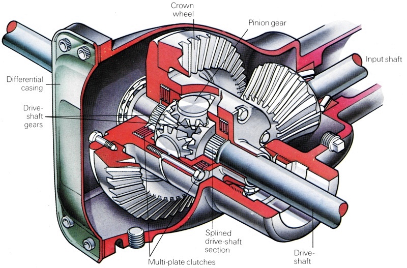
Eventually, from the simple pair of bevel gears a more complicated arrangement was developed - the differential. This allowed the driven wheels to rotate at different speeds while still splitting the torque equally between them. The modern final drive, therefore, consists of two parts: one to turn the drive through a right angle and, incidentally, to gear down the drive according to the needs of the car and the other designed in order to allow differential movement of the wheels. The first need, harking back to the original bevel gear drives, is served by the crown wheel and pinion. The differential unit, serving the second need, is carried within the crown wheel housing and is attached to the crown wheel. The drive enters the final drive unit from the propeller shaft (or, in the case of a FWD installation, directly from a spur or bevel gear) by means of a short input shaft on which the pinion gear is mounted. The pinion engages with the much larger crown wheel in order to turn the drive into the line of the axle.
Crown Wheel and Pinion
The earliest crown wheel and pinion arrangements used straight-cut teeth because these were the easiest to make. However, straight-cut teeth mean that the drive is carried by one tooth at a time, which can lead to noise and vibration unless all the teeth are exactly evenly spaced and exactly the same shape. To overcome this problem designers moved to the spiral bevel form in which the teeth of both the crown wheel and the pinion are curved. With this tooth form, two or possibly even three pairs of teeth are in contact at the same time and smoother running results, together with more even wear. A further development was intended to reduce the amount of space taken up in the passenger compartment by the transmission tunnel. This could be achieved if the propeller shaft could be lowered; but as long as the shaft had to meet the final drive at the centre-line height of the rear axle, this could not easily be done. The answer was to lower the point at which the propeller shaft met the final drive, so that instead of pointing straight at the axle centre line, the axis of the shaft ran some way below. In this way propeller shafts could be lowered by a very useful 150 mm (6ins) or more where they ran through the passenger compartment.
The penalty was that a new gear tooth form had to be developed to enable the two "out-of-line" gears to mesh. When the gears are in-line, the teeth are only in rolling contact; but in the out-of-line "hypoid" form, they have to slide as well as roll. This advance placed new demands on lubrication and these were met by the development of extreme pressure (EP) oils. If a non-EP oil is used in a hypoid drive, it breaks down quickly under the stress and gear damage soon follows. One other form of drive also allows the propeller shaft line to be lowered. This is the worm-and-wheel drive which could almost be considered as an extreme form of hypoid in which all contact is sliding rather than rolling. Peugeot used worm drive for a long time, up to and including the 404 model which was notably quiet in operation but needed an even more specialized lubricant.

The worm-and-wheel drive was used by Peugeot up to the 404 model. It was extremely quiet in operation and alled the propeller shaft to be lowered, thus leaving more room inside the car for passengers. The only downside was that it required a specialized lubricant to work effectively over the life of the vehicle.
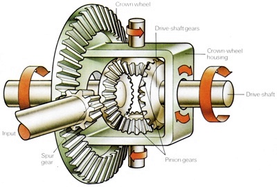
The function of the differential is to split equally the torque and feed it to the road wheels while allowing the wheels to turn at different speeds if necessary. When entering a bend, the drive shaft gears will rotate at different speeds. They are able to do so because the pinion gears can rotate on their shafts allowing one drive-shaft to turn more quickly than the other. When travelling straight ahead, there is no relative movement between the drive-shaft or pinion gears so that they and the differential casing all rotate at the same speed.
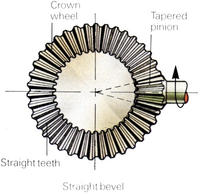 The earliest crown wheel and pinion units used straight cut teeth to transfer drive. The earliest crown wheel and pinion units used straight cut teeth to transfer drive.
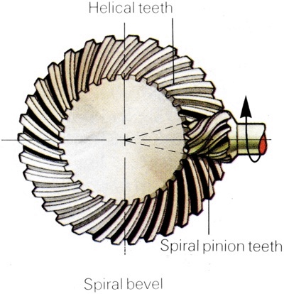
With a curved tooth form, two or three teeth were in contact at the same time.
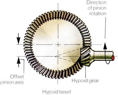
An offset hypoid bevel arrangement allows the propeller shaft to be lowered.
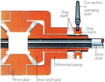
In the differential lock, a dog-clutch locks the driveshaft gears to the differential housing, forcing them to rotate at the same speed. An alternative design locked the pinion gears. |
The Hypoid Drive
The hypoid drive is now universal except in FWD cars where the need to lower the propeller shaft does not arise. In those cars, such as the BL Mini where the final drive shares its oil supply with the engine, it would not, in any case, be possible to use hypoid drive since the engine oil would not be a suitable lubricant. Transverse-engined Front-Wheel-Drive cars use a spur gear drive direct to the crown wheel, while those FWD cars that have in-line engines, such as the Renault 5 and 18, use a spur gear drive to a short idler shaft carrying a normal pinion gear with spiral bevel teeth. The other important function of the crown wheel and pinion is to provide the final step-down ratio in the drive line from the engine to the drive wheels. The crown wheel is always a lot bigger than the pinion, so the final drive is a reduction - the wheels rotate slower than the propeller shaft. Most car final drives give reduction ratios between 3:1 and 5:1, though commercial vehicles and competition cars may use higher ratios. There tends to be a limit to how low the drive ratio can be made, because either the crown wheel must be made smaller (leaving too little room for the differential) or the pinion made bigger (which makes the whole final drive unit bulkier).
The transmission designer is limited in his choice of final drive ratio by several factors. All ratios are obtained by meshing two sets of gear teeth, so the designer can only work with combinations of whole numbers. To keep tooth sliding speeds within bounds, the pinion must have a reasonable number of teeth - seven as a practical minimum but more are preferable. This means that the crown wheel may have anything from 25 to 45 teeth. However, there is a further problem. If the number of teeth in the crown wheel is an exact multiple of the number of pinion teeth-or indeed, if the relationship between the numbers is at all simple-there is a danger of resonance setting in. This means that the natural frequencies of the two gears will act in "sympathy" and consequently cause noise and, in severe cases, gear damage. This is why final drive ratios of exactly 3:1, 4:1 or any other combinations of whole numbers are never used in this manner.
To keep the problem to a minimum, transmission designers prefer to use primary numbers of teeth on one or both gears. Thus 11 and 13 are good choices for the pinion teeth, especially in larger and more powerful cars, while 37, 41 and 43 are often used for the crown wheel. Familiar final drive ratios for powerful cars include 3.08:1 (40 crown wheel teeth and 13 pinion teeth), and 3.09:1 (34/11); large family saloons may have 3.31:1 (43/13) or 3.45:1 (38/11). Familiar ratios in smaller cars are 3.89:1 (35/9) and 4.11:1 (37/9). In all of these cases the fraction involved is a complicated one and consequently there is no chance whatsoever of the gears resonating. The gear ratios in FWD cars often look unfamiliar because the gearing-down is done in two stages, taking the drive from the gearbox to a transfer gear and from the transfer gear to the final drive. Further details on FWD final drive are described in greater depth in a later article.
The Differential
Once the engine's torque has reached the crown wheel, it still has to be split equally and fed to the wheels, while allowing the wheels to travel at different speeds. This is the function of the differential which consists of a drum bolted to the crown wheel and carrying two bevel pinion gears. These in turn mesh with two more gears, one on the end of each drive-shaft. As long as the car is moving in a straight line, each wheel is travelling at the same speed and there is no relative movement between the gears mounted on the drive-shafts. They and the differential casing all rotate at the same speed. The two smaller pinion gears do not rotate on their shafts at all but simply act as links transferring the drive from the crown wheel, via the differential casing, to the drive-shaft gears themselves.
When the car enters a bend, or if one wheel starts to slip due to wheel-spin, the drive-shaft gears will start to rotate at different speeds. They are able to do so because the small pinion gears then start to rotate on their shafts, permitting the differential movement. At the same time, the differential casing continues to be driven by the crown wheel with the result that the pinion wheels are being carried round as well as rotating on their axes. Because they are being carried round, and because whatever their own rotation they are still in mesh with the drive-shaft gears, they still transmit the drive torque - and consequently split it equally between the two driven wheels.
It is possible to look at the mechanism in another way. If the resistance to movement of one wheel is less than the other, as might happen if it hit a slippery patch, the drive will tend to accelerate that wheel, because its drive-shaft gear will be easier to push round. The acceleration will cause the pinion gears to rotate and will continue to do so until the torque is again in balance, by which time the slipping wheel may be rotating a lot faster than the other. In other words, the differential not only allows the wheels to rotate at different speeds (which is generally understood) but functions as a highly accurate torque-splitter, a task that is less widely appreciated by most people.
Differential Problems
The differential gear described works well in most circumstances, but has one serious limitation. If one wheel has little or no resistance to motion - if it is on sheet ice, in mud or simply off the ground - virtually no torque can be transmitted to it, because it will spin faster and faster until part of the mechanism breaks. Since the differential acts as a torque splitter, this means that virtually no torque can be transmitted to the other wheel, either. The differential pinions spin helplessly, the slipping wheel spins furiously and the other, "good" wheel simply stops rotating. The problem is most serious for two kinds of drivers - one who uses a vehicle off-the-road, where mud and generally slippery conditions are encountered, and the competition driver who needs to maintain traction at all times to maintain competitive speeds. The two situations are different in most senses and consequently different solutions are offered in each case. For the off-the-road driver, the main requirement is to keep going and the simplest way of doing this is to provide him with some means of locking the differential.
In practice, a differential lock works either by clutching the drive-shaft gears to the differential case, forcing them to rotate at the same speed as the case itself, or by locking the differential pinion gears so that they cannot rotate on their shafts (again forcing the drive-shafts to rotate at the same speed). Dog clutches are usually used for this and because of the nature of dog clutch design this means that it is impossible to engage the device while the drive is under any pressure and the vehicle therefore has to be brought to a standstill first. Caution has to be exercised in providing a differential lock, since all the available torque - not just half of it as would be the case with ordinary differential systems - will be applied to whichever road wheel has the better grip.
In general terms, therefore, the drive-shafts and gears need to be twice as strong as in a design which cannot be locked. The problem is even more severe in four-wheel drive (4WD) vehicles, which can have differential locks on each end, that is, in each driven axle, and a third lock in the transfer gearbox which enables the vehicle to be kept moving as long as one of the four wheels can find any grip. 4WD vehicles are covered in greater detail in another article.
Limited-Slip Differentials
A differential lock is of little use to the racing driver. For one thing, his problem is not so much slippery conditions but rather the tendency of one driven wheel to lift and spin during extremely hard cornering and he obviously cannot stop to allow a dog clutch to engage to counteract this. This apart a solid axle (which is in effect what a final drive and its associated shafts become once the differential is locked) can be detrimental to a car's handling. The last thing a racing driver needs is a sudden attack of bad handling as the price of extra grip. Despite this, during one Grand Prix season several teams experimented with locked differentials. Only one driver, Mario Andretti, found any advantage in this but he was obliged to adapt his driving style to suit the new handling characteristics of his car. This car was, in any case, different from its major rivals at the time, being the first Grand Prix machine to exploit the principles of "under-car" aerodynamics or "ground-effects" and this may have had an influence. Most other drivers found that the locked differential induced an unacceptably high level of understeer and the experiments consequently faded.
The need to provide a better answer has, in the past, given rise to several forms of limited-slip differential. In all cases, the idea is to provide some measure of extra friction on the way to the spinning wheel, so that some torque can still be applied to its drive-shaft. Whatever torque can be applied to this shaft can also be applied to the other shaft, so that twice the amount of torque which will spin the slipping wheel remains available to propel the car in the appropriate direction through the other wheel. Skilled drivers, especially in Scandinavia and other countries where snow is common, are aware that the handbrake works in this way if it is applied to the driven wheels. If it is pulled on gently, to apply some friction to the wheels without actually locking them, the spinning drive-shaft can accept some torque and a measure of drive may be applied to the opposite wheel. This is one reason why all of the FWD Saab cars have their handbrakes acting on the front wheels and not the rear wheels.
Although it is effective, applying the handbrake is a crude and makeshift way of limiting the slip. It can hardly be considered by a racing driver who is working hard to stay on the limit of cornering ability especially as pure single-seater racing cars do not have handbrakes. Some device is needed which will apply the friction automatically. The pioneering differential device was produced by the German firm of ZF in the 1930's. It used two cams, one attached to each drive-shaft, driving a number of plungers located in a frame on the differential casing. The two cams had different numbers of lobes - usually 11 on one and 13 on the other. As long as they rotated at the same speed there was no effect but as soon as one wheel started moving faster than the other the cams "squeezed" the plungers to obtain friction between drive-shafts and differential casing.
Modern limited-slip differentials work in another way. As long as there is no relative movement between the wheels and their drive-shafts, the differential pinions simply push round the drive-shaft gears. Once the speeds are different and the pinions begin, to rotate on their axes, they try to push themselves away from the drive-shaft gears. This is a reaction that occurs with all gears in driving contact and normally it is restrained by the bearings. In modern limited-slip differentials, however, this effect is used to obtain the extra friction required to prevent wheel-spin. The drive-shaft gears, mounted on splines, are allowed to push themselves away from the differential pinions just sufficiently to apply some form of brake. Borg-Warner built such a differential with cone-type brakes which were rather like an old-fashioned cone clutch assisted by preloaded springs. The most popular type today uses multi-plate clutches behind the drive-shaft gears. These clutches are like small versions of those used in automatic transmissions. They are compact and easy to install in a drum-shaped differential case and they have the advantage that the number of clutch plates and the friction material can be varied to suit the particular application involved.
It is important to remember that these differentials are exactly what their name implies - "limited" slip devices. They do not lock completely and prevent wheel-spin; otherwise they would function in the same way as the differential locks discussed earlier and would give rise to the same handling problems. The effectiveness of a limited-slip differential is expressed as a percentage of the driving torque it can deliver to the "good" wheel when the other is free to spin. It is not a case of the more the better; a balance has to be struck between the best traction and the best handling. This is why the tuning of many cars includes experiments with various degrees of slip limitation. Too much limitation leads to understeer and this is soon noticed even in a powerful road car with too strong a limited-slip unit, although racing cars often employ a stronger limited-slip differential because to some extent the chassis can be tuned by changes to the suspension and aerodynamic aids to offset the natural understeer.
Apart from their expense, limited-slip differentials are not used in medium-sized cars because the handling problems they are designed to overcome simply do not arise. Their use in production cars really started in America during the days of the "horsepower race" before the advent of
air pollution and fuel consumption regulations, when the big V8 engines of the 1960s used to produce massive torque figures - anything up to 69 kg/m (5001b/ft). When the throttle was opened quickly, the build-up of torque in the drive line could rock the whole car sideways on its springs quite violently. This in turn could unload one rear wheel enough to start it spinning and the result was severe tyre wear, poor traction away from a standing start and, occasionally, serious axle-tramp problems. The limited-slip differential was the answer, to this situation and became a standard fitting on what became known as the "muscle" cars with engines of 6-litres or more in relatively light bodies.
On European high-performance cars, limited-slip units were used mainly to avoid the loss of traction caused by a driven wheel lifting and spinning during hard cornering. There is also, of course, the bonus of better grip during standing starts when the driver uses a considerable amount of power. Limited slip differentials were offered as optional equipment on most large Australian sedans in the 1970s onward and were standard equipment on Australian-made Fords fitted with the 5.8-litre, V8 engine.
Clearance and Bearings
Whether or not a final drive unit is of limited-slip variety, it faces the same basic problems of location, adjustment and wear of its moving parts. Bevel gears are especially sensitive to adjustment and poor tooth contact can result from the gears being either too close or too far apart. Poor contact usually results in harsh noise as well as more rapid wear. Provision is therefore made in all final drive units for the gears to be re-set, usually by means of shims, to adjust their clearance. Even when the gears are correctly set to begin with, wear takes place and older differentials become more noisy. In modern cars, however, it is not unusual for the final drive to last the useful life of the car.
Because bevel gears also try to thrust themselves away from each other, they need to be restrained as well as located. In particular, the input shaft to the pinion must be properly held against thrust as well as side loads and it generally runs in two taper roller bearings. The drive-shaft gears on the other hand are generally splined on to their shafts so as not to transmit any end load to the wheel bearings and to allow the shafts to be removed, in the event of breakage, without having to dismantle the whole final drive assembly. The thrust load from the gears is taken out by thrust washers between the gears and the differential casing. The crown wheel and differential usually run on plain ball bearings.
The final problem in differential design is that of oil sealing. The oil contained within the unit has three possible ways of escape - forward along the input (propeller) shaft or sideways along either of the two drive-shafts. In a non-independent or "live" axle, oil leakage along the drive-shaft is particularly serious because the oil can travel down the axle tube and contaminate the rear brakes - drastically reducing their efficiency. Positive sealing arrangements in the form of labyrinth seals or scrapers are usually provided for all three shafts to avoid such problems.