Leaf, Torsion Bar, Coil, Rubber and Gas-Filled
We all know what a spring is. They are everywhere, from the humble ball point pen to the car parked in your drive (we hope its a classic!). And we all know what a spring does - that is to compress or extend to an extent depending upon the force applied to it, and afterwards assume its original dimensions.
Five types of spring are commonly used in motor vehicle suspension systems: leaf, torsion bar, coil, rubber and gas-filled devices are well known. The extent to which a spring deflects under load is known as the 'spring rate'. Each of the above types of spring can be manufactured either with a linear spring rate (so that within its designed operating limits its deflection is directly proportional to the load) or with a non-linear spring rate (so that its deflection becomes less against a steadily increasing load).
The Leaf Spring
A spring with a non-linear spring rate is desirable in motor vehicle suspension systems; the spring will be required to provide a comfortable ride when the motor vehicle is loaded with only the driver, and yet be firm enough to support full load. Right up until the mid 1980s the leaf spring was the most common form of spring used for suspension systems. It had the advantage of enabling a designer to produce a very simple and cheap suspension system; even though such a system came with considerable drawbacks.
A leaf spring consists of a number of leaves of chrome vanadium steel. These laminations are interleaved with an anti-friction material, or separated with pads of such material, to enable them to slide on one another as the spring flexes. A small bolt is usually fitted through the leaves at the centre of the spring to ensure that they would remain in alignment. Clamps were fitted to keep the laminations together, and a rubber bump stop was fitted between spring and chassis to prevent damage if the suspension 'bottomed'. Conventional rear spring rear-suspension systems used the spring not only to cushion the vehicle from road shocks, but also to locate the wheels and axle relative to the chassis. In such a system, a solid rear axle was secured to the centres of two longitudinal springs by 'U' bolts and clamps.
The front end of each spring was secured to the chassis via a rubber bush and the rear end was allowed the lateral movement caused by the bending of the spring, by a shackle, which was also mounted in rubber bushes. Although the spring will absorb road shocks, it is sufficiently stiff to accept the torque reactions of acceleration and braking forces. It was possible to see the exposed leaf springs on some vehicles tending to 'wind up' as the driver accelerated from rest. On high-performance cars, this wind-up could become excessive and interfere with the spring's ability to undertake its normal suspension duties, resulting in a loss of traction on uneven surfaces.
Radius Rods and Tie-Rods
To prevent this, an additional linkage may have been fitted by the factory or as an aftermarket accessory, which would absorb any tendency for the axle to rotate. This linkage may take the form of radius rods, rigidly fixed to the axle and attached to the chassis at points geometrically equivalent to the front spring attachments. Torque from the drive shaft would cause a solid rear axle and leaf spring arrangement to tend to lift one wheel, which would produce loss of traction. Fast cornering would produce large lateral forces on the axle but transverse displacement could be prevented by transverse or diagonal tie-rods which would allow vertical movement while absorbing the cornering forces.
Beam Axles
Eventually, the number and complexity of the linkages required for satisfactory roadholding raised the cost of this basically sensible, cheap system to near that of independent suspension systems, which were always able to give greater performance. Beam axles are another suspension system that has been left to the annals of history - mainly because the high unsprung weight and sensitivity to wheel wobble were undesirable. The exception are commercial vehicles which for many years relied on a beam axle at the front. The lower operating speeds of these vehicles eliminated the disadvantages and the leaf spring and beam axle arrangement provided a simple and robust suspension system.
Leaf springs were fitted transversely to some vehicles, with the centre attached to the chassis and the two ends of the axle. Fiat refined this idea by using two chassis mountings at points well outside the centre of the spring. This produced an anti-roll effect; as one wheel rose, a simple lever effect through the spring tended to raise the opposite wheel. Quarter-elliptic forms of leaf spring were also used. They were mainly limited to lightweight applications, such as standard box type trailers, because the load at the point of attachment to the chassis was not well distributed. They were occasionally mounted transversely, with a stub axle welded to the outer end, to form an independent suspension system for small trailers.

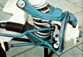
Coil spring assembly from Ford, circa 1980.
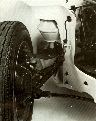
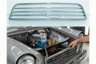
The front suspension of the Austin Allegro, with the Hydragas unit clearly visible. |
The Torsion Bar
A torsion bar is a spring that derives its elasticity from its ability to twist under load and return to its original state. For a given load, the deflection of a torsion bar increases with its length. Torsion-bar suspension systems were typically from the mid 1970s.
Renault used torsion-bar suspension systems on their R16 series. The exceptionally large rear-wheel movements on these cars required a transverse bar as wide as the car. One end was fixed and the working end was attached to a swinging arm. To fit two torsion bars right across the car, Renault had to step one wheel slightly ahead of the other.
Either a solid or a laminated torsion-bar spring may have been used. The laminated type had the advantage that the spring rate may be adjusted simply by adding or removing laminations. If a solid torsion bar were to break, the vehicle would probably be immobilized but in the laminated type, failure of one lamination was not serious and the vehicle would remain mobile. An
anti-roll bar was often a form of torsion bar, arranged to transmit the movement of one wheel to the wheel on the opposite side of the vehicle. In some
suspension systems, such as the MacPherson strut arrangement on some UK Fords, the
anti-roll bar located the front wheels in a fore-and-aft direction in addition to performing its duties as a spring.
Coil Springs
As cars became more refined, manufacturers turned to independent suspension systems employing coil springs. In such systems, the spring only absorbs wheel movement; the axle and wheels are located by linkages. A coil spring can be considered to be a torsion bar which has been coiled. An increase in length (by increasing the number of turns) will provide a greater deflection for a given load. Removing a turn or two from a coil spring in order to improve roadholding will both lower the vehicle's centre of gravity and produce a firmer ride. Rubber is used as a spring material, the first many will remember as that used on the Leyland Minis, in a suspension system which provided a limited degree of comfort but a degree of stability that enabled the little car to hurtle round corners at incredible speeds.
Rubber Springs
There are distinct advantages to be obtained from using rubber as a spring material. A suspension system of this material can be designed. to occupy a very small space and the spring itself can 'be designed with a non-linear deflection. After five years' production of rubber-sprung Minis,
BLMC fitted the
Hydrolastic system that had proved very successful on the
1100 series. Unfortunately, the short wheelbase on the Mini produced an unacceptable degree of pitching and BLMC eventually reverted to the simple rubber cones and telescopic dampers. Independently sprung wheels have a disadvantage in that the attitude of a vehicle will vary considerably according to its loading.
This could upset the
handling properties and the headlight alignment. In efforts to minimize this disadvantage, designers devised systems that connected the springing medium of independent suspension units in such a way that movement of one wheel is transmitted to the other wheel on the same side, or to all three other wheels. Three types of coupling may be used; mechanical, hydraulic or a pressurized. gas system. Because of the complexity and cost, very few cars use a system whereby all four wheels are interconnected. On the simplest type of system, using a mechanical coupling in the form of a spring, wheel movement is transmitted via a bell-crank, through a tension spring to the other wheel. The effect is that if one wheel rises, the coupled wheel also tends to rise. This system reduces changes in attitude under varying load conditions and reduces pitching.
The Hydrolastic System
BLMC developed a more refined form of coupled suspension in the form of the
Hydrolastic system fitted to their
1100 and
1800 series. Springing was effected by a chamber's expansion within an enclosing rubber spring. When a wheel rose, it displaced fluid through a small orifice into the flexible chamber. Damping was obtained by virtue of the small orifice through which the displaced fluid had to flow. Coupling was obtained by a small-bore tube which connected the spring chambers of both wheels on one side of the
automobile. Thus, as one front wheel rose, fluid was displaced into the chamber of the rear wheel on the same side, reducing any tendency to pitch. The rear suspension was also in an extended condition, as it waited to absorb the bump. This system had the advantage of being fairly soft at low speeds and harder at high speeds, when the damping orifice offered a greater restriction to an increased fluid flow.
The Hydragas System
Further development of the
Hydrolastic system produced the
hydragas system; in this, the springing medium was compressed gas. Although it was extremely comfortable in normal use, high-speed driving over poor road surfaces could become unpleasant. A more sophisticated, and considerably more expensive, pressurized gas suspension system was to be found on the larger
Citroens, On this type of system, air was supplied to the suspension system from a compressor driven by the engine. Such a system could have a manual control to stiffen the suspension, according to the road conditions, by increasing the pressure. There may also be devices fitted which will reduce or increase the pressure in the system automatically, with changes in load.
Maintaing Your Classic
Most car manufacturers specify little or no maintenance for springs but it is worthwhile making an occasional check to ensure that they continue to operate efficiently and quietly. Leaf springs should be scrubbed with a wire brush, to remove any dirt and rust. Examine each leaf to see that it is not cracked and check that any anti-friction inserts are not missing or broken. If the spring is greased and does not employ anti-friction inserts, examine the area where the leaves rub. If wear has occurred, the spring should be renewed. Check that the spring clamps, and the 'U' bolts securing the axle are tight. Examine the spring shackles carefully; their worn condition may not be immediately noticeable.
Check that any rubber components have not deteriorated and, finally, grease the leaves well. Torsion bars of the laminated type should be wire-brushed and examined for broken laminations, if accessible. Check that mounting bolts are tight and grease the laminations as recommended. Solid torsion bars' and coil springs require 'virtually no attention, although there may be a rubber insert between the top of a coil spring and the chassis. This should be checked to ensure it has not deteriorated or slipped out of position. Rubber springs require no maintenance and the pressurized air systems will be subject to specialized maintenance, specified by the manufacturer.