There are 3 temperatures of interest to the motorist; that of the water in the
cooling system, that of the engine lubricating oil and that of the outside air. As auto manufacturers enhanced the dashboards from the rudimentary speedo and fuel gauge, they used two types of gauge: the mechanical and the electrical. In the mechanical gauge, the sensing element was a metal bulb, containing a fluid that had a high coefficient of expansion and a low freezing point, connected by a capillary tube directly to a diaphragm or Bourdon tube.
When heated, the fluid expanded, causing the gauge pointer, connected to the diaphragm or tube, to move across a short scale. An amplifying mechanical linkage could be included in the instrument case so that a longer, circular scale could be employed. The electrical gauge used a thermister bead, also mounted in a metal bulb, as the sensing element, or transmitter.
The Thermister
The thermister is a device with a variable electrical resistance, determined by the ambient temperature: when cold, its resistance is high; when hot, its resistance is low. The vehicle's
battery provides power to operate the gauge, when the ignition is switched on. The indicating meter is of either the common moving-coil or the bimetal-strip type. One of the earliest types of water temperature gauge was a thermometer mounted in perhaps the easiest and most visible position at that time - on the
radiator cap. A later type suitable for both oil and water temperature measurement employed a bimetal-strip device, enclosed within a heating coil, for both the transmitter and the dashboard indicator.
When the engine is first switched on, the
battery alone heats the coil; the mean
battery current is therefore maximum and the indicator metal strip warms up, moving the pointer, to which it is attached, to the cold position. As the engine temperature increases, the water (or oil) has its own heating effect on the transmitter bimetal strip, so that less and less current is drawn from the
battery. Thus there is less heating of the indicator bimetal strip, which cools, moving the pointer towards the hot position.
Water Temperature
The most important temperature to know is that of the cooling-system water. Accurate measurement, however, is not required; calibration is often no more than 'Cold' rising to 'Hot', with the normal operating temperature (80 to 85°C) somewhere between the two. The sensing element is usually fitted near the top of the cylinder block or in the thermostat housing. Since it is essential that a driver be aware of any unusually high water temperature, most water-cooled vehicles are fitted with a cooling-system gauge. A high reading could indicate any of the following faults: fan belt broken or slipping (on belt-driven fans); electric drive failed (on electric fans);
radiator blocked inside (loose scale, for example) or outside (leaves, insects etc); collapsed
radiator hose; cylinder block furred; shortage of water in the system; failure of water pump or thermostat; failure to remove
radiator muff or raise blind.
Very hot weather, especially in 'stop-start' traffic, may also produce a high gauge reading, but the gauge should return to normal under cooler conditions. After a cold start, the pointer should indicate normal operating temperature within about ten minutes. If the sensing element is installed in the thermostat housing or the
radiator header tank, a 'Cold' reading should be obtained until the engine is at or near its operating temperature, when the thermostat suddenly opens. A constantly low reading may indicate a faulty thermostat, gauge or sensing element.
Types of Water Temperature Gauges
There are four main types of water temperature gauge. The most common are the semi-conductor units which may incorporate bi-metallic or moving iron indicator gauges. Again, the bi-metallic gauges use a voltage stabilizer. Less common is the thermal gauge. On this the pointer needle will rest on the "Hot" position when the ignition is switched off. This type is fitted almost exclusively to older cars such as the Jaguars of the mid 1960's. All three of the above gauges consist of an instrument head (the gauge itself) and a transmitter bulb. Finally, there is the mechanical water temperature gauge. Here, a temperature-sensitive bulb is fitted as part of the instrument and it is joined to it by a capillary tube. This tube contains volatile liquid and is completely sealed.
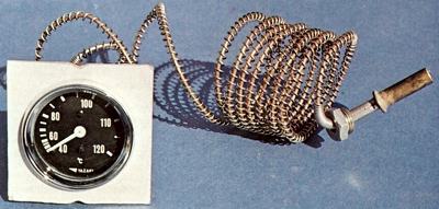
Old Yazaki water temperature gauge, operated via a capillary tube rather than an electrical circuit. The sensing bulb is screwed into one of the engines water passages and as the engine heats up, the fluid in the bulb and the tube expands and causes the needle to move.
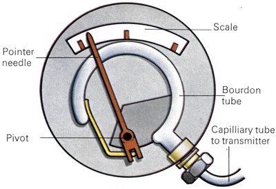
The mechanical water gauge is operated on the Bourdon tube principle. The tube expands as the volatile liquid within it is heated by the water around the transmitter in the engine. The tube then moves the needle thus giving a reading on the gauge. |
On no account should any attempt be made to open the capillary tube. If it is disturbed, the gauge will cease to function accurately. The gauge operates on what is known as the Bourdon Tube principle. Inside the gauge there is a coil of oval-section tube which joins the exterior capillary tube. When the water temperature increases the pressure this causes the oval-section tube to move in an outward direction and so moves the pointer needle around the dial. The chief benefits with this type of instrument are that it is very accurate and that it adjusts quickly to any change in temperature. With the bi-metallic, moving iron and thermal types of gauge, the electrical connections should be checked first and repaired, as necessary, as described above. Checking the gauge: To test a bi-metallic gauge, or a moving iron gauge, repeat the test outlined for checking a fuel gauge. In this instance, of course, the gauge will register "Hot" and "Cold" not "Full' or "Empty".
If a moving iron gauge is working correctly and the wiring is satisfactory, the transmitter unit must be at fault and should be replaced. On a bi-metallic gauge, however, it is also necessary to test the voltage regulator. To check a thermal type gauge you will have to use the substitution test. To do this you will have to fit a new transmitter unit so that the gauge can be tested against a transmitter unit that is known to work properly. Make sure that you obtain the correct replacement by checking the serial number on the unit. The transmitter unit is fitted to the cylinder head of the car's engine and is usually mounted near to the thermostat housing. To remove it, pull off the electrical lead and then use a spanner of the correct size and unscrew the locking nut which is separate from the main transmitter.
On other types the locking nut is part of the unit. Do not use a spanner that is not the right size or an adjustable spanner as the bulb is made of brass and the faces of the nut can easily become burred and rounded, making removal very difficult. The new transmitter may be fitted with a small gasket, so make sure that this is not lost. Apply a little gasket compound to both faces of the unit and screw it into place, tightening it firmly. Replace the lead and then try the gauge. If there is still no reading, the gauge is faulty and should be replaced. Finally, to check a mechanical water temperature gauge you will first have to ensure that the capillary tube is fitted correctly to the car's engine as incorrect fitting can prevent an accurate recording of the engine's temperature. The bulb on the transmitter should always be immersed in coolant and the tubing should be lightly clipped to a part of the engine which is approximately 75 to 100 mm (3 to 4ins) away from the transmitter bulb.
Up to this point there should be no coils in the tubing and it should not be curved in a radius of less than 25 mm. The tubing should then run to the bulkhead of the engine bay, being clipped every 100 to 150 mm (4 to 6ins). After the last clip, there should be three or four coils of not less than 50 mm diameter. The tubing should then run straight to the back of the instrument. When you are sure that the tubing is properly located, drain the coolant to below the level of the transmitter bulb. You can do this either by using the radiator drain tap or the tap on the side of the cylinder block. Next, remove the transmitter bulb, taking great care not to damage the tubing. Dip the transmitter into a receptacle containing boiling water and then have an assistant switch on the ignition. The gauge should indicate 100 C or 212 F quite quickly.
If it does not do this it is faulty and the complete unit will have to be replaced. Checking the transmitter unit: On bi-metallic and moving iron water temperature gauges the transmitter units can be checked by using the method described above for a mechanical gauge, but take note to carefully earth the body of the transmitter. Checking the voltage -stabilizer: On bi-metallic gauges the voltage stabilizer can be checked by using the method outlined above for a bi-metallic fuel gauge.
Oil Temperature
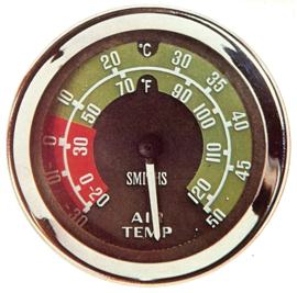
Any suggestion of rising oil temperature, especially if coupled with falling oil pressure, is an alarm signal not to be ignored. A failing oil pump, shortage of oil, blockage or a 'run' bearing, all very serious defects, can cause the oil temperature to rise dramatically. However, such is the reliability of modern 'family car' engines that only a warning light, set to operate when the oil pressure has dropped to the safety limit, is normally provided. The oil temperature gauge with an informative scale is normally confined to sports, high-performance and racing cars. Although such a gauge is rarely fitted in a mass-produced vehicle, knowledge of the outside air temperature (OAT) can be advantageous, especially at night, when the temperature may drop below zero quite unexpectedly.
Awareness that freezing conditions are approaching alerts the motorist to adjust their driving technique to meet them. The OAT gauge is also of value in the higher sector of its scale, since it enables the driver to determine when the
radiator muff or blind should be opened or when carburettor-air winter/summer settings should be adjusted. Transistorised circuits, described in the electronic journals, have the conventional meter replaced by a flashing light, adjusted to operate at or near freezing temperature. When installing all capillary type gauges, or maintaining a vehicle with one fitted, it is of vital importance that the capillary tube is not cut, kinked, twisted or disconnected from either the bulb or the gauge. Surplus tube must be loosely coiled, and there must be coils between the engine and the first attachment to the chassis, to allow the engine mountings to flex without putting strain on the capillary tubing. The manufacturer's fitting instructions must be followed in detail.
When fitting a water temperature gauge, if neither the cylinder block nor the thermostat housing is tapped to receive a transmitter element, the header tank of the
radiator or one of the hoses are about the only practicable locations, although it may be possible to buy a special thermostat housing. When fitting an oil temperature gauge, the transmitter bulb should be installed fairly low down in the side of the sump. If no tapping is provided, it is essential to ask the manufacturer of the vehicle exactly where the transmitter may be located. The sensing element for an outside air temperature gauge is installed low down at the front of the car, since the temperature of the air nearest to the road surface is of the greatest importance. The usual location is behind the front bumper, but clear of any influence of the
radiator and protected from rain or surface water spray which may produce a super-cooling effect by evaporation.