The very first motor driven vehicles, such as Edward Butler's 1885 tricycle, had virtually no transmission system, the driving wheel spindle constituting a crankshaft to which the pistons were linked by long connecting rods in an emulation of steam locomotive practice.
Thankfully car designers soon learned that the inability of the
internal combustion engine to furnish controllable torque from zero rpm made some sort of complex transmission system essential. While there are a handful of vehicles that do not have one (jet powered
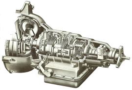
Land Speed Record vehicles come to mind). Every modern car has a transmission system incorporating at least four component sub-assemblies, but the number can rise to seven: a clutch, a gearbox, an overdrive, a propeller shaft, the final drive or 'axle' gearing, the differential gearing, and the half-shafts finally transmitting torque to the driving wheels.
They do not always appear in that order: sometimes the propeller shaft comes first in the drive line, sometimes it lies between the clutch and gearbox, sometimes it can be traced in vestigial form as a quill shaft passing through the transmission aggregate of a mid-engined or rear-engined car; sometimes the necessary differential action is provided by the gearbox or whatever takes its place, as in early versions of the
Daf Variomatic Transmission.
The Clutch
It is normal and fairly logical for the first item in the drive-line to be the clutch. Its function is to permit progressive engagement and disengagement of the engine from the rest of the driveline, the principle requirement being ease of moving the car away from rest with the engine running, and a secondary consideration being ease of gear-changing. In its conventional simple form, the clutch is probably the crudest piece of machinery in the car, an engine-driven disc being controllably clamped to another so that friction and clamping forces will combine to make them rotate as one. The slower it turns, the larger it needs to be in order to transmit a given power; the larger its diameter, the more power it can manage at a given speed, but the more highly stressed it will be mechanically.
The Multi-Plate Clutch
Also, the greater the difference between the outer and inner diameters of the friction surfaces, the greater the difference in rubbing velocities when the clutch is deliberately slipped in controlled engagement, and therefore the greater the risk will be of local overheating or other damage. Most of these problems can be resolved if necessary by multiplying the number of clutch plates and reducing their diameters. Clutches of the multi-plate type take up the drive very smoothly, but do not always disengage as cleanly as they should, which was why double declutching was unnecessary when changing down in a
Bugatti.
The multi-plate clutch of the
Bugatti was unusual on two other counts, first in being lubricated by partial immersion in a mixture of oil and paraffin, and also in being reliant on a system of weights and levers to increase the clamping force as engine rpm increased, the centrifugal loads being adjustable so that the clutch could be made very fierce or docile and sensitive, Wet or oil-immersed clutches were popular in the late 1930s, and centrifugal assistance has often been contrived, notably in the so-called 'traffic' clutch of pre-war Rileys fitted with Wilson pre-selector gearboxes, and then in the Daf transmission which was steplessly variable between fairly wide limits and only needed a clutch for starting and stopping.
The Fottinger Fluid Coupling
Centrifugal assistance can act simply as a servo, making the pedal action lighter in low-speed driving; all other attempts to create adequate clamping forces with light pedal action resulted in either uncomfortably long pedal travel and troublesome adjustment problems, or the fierceness of the cone clutch which was generally abandoned in the late 1920s. By the end of that decade the Fottinger fluid coupling was being tried, notably by Daimler in Britain, in an attempt to ensure perfectly progressive take-up of the drive and to relieve the driver of the need for skill at the pedal. This was a success when combined with epicyclic gearboxes of the Wilson type, and led in due course to the automatic transmission.
The Gearbox
There have been countless variations on the simple two-shaft gearbox that the great French pioneers Panhard and Renault popularised in the 1890s. The number of ratios offered has varied from two to eight, according to the torque characteristics of the engine, the weight of the vehicle, and the performance expected of it. Sometimes one of the ratios has by-passed the secondary or lay shaft to provide a direct drive of 100 per cent mechanical efficiency, this usually being the highest gear generally most in use, while the other ratios would involve at least two pairs of meshing gears, bringing the efficiency down to 96 per cent or less.
Sometimes all the gears are indirect, each involving one step down through a pair of meshing gears; mechanical efficiency is approximately the same in all ratios. The indirect gears of early boxes involved sliding pinions into engagement, but constant-mesh gears clamped to their shafts by axially engaged teeth (dog-clutches) proved easier to manage, and allowed the gears to be formed with helical teeth instead of straight ones, mechanical efficiency being sacrificed to quietness. From this it was a short step to the modern
synchromesh gearbox, in which miniature clutches equalise the speeds of rotation of the dogs before they engage.
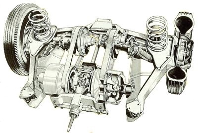
The Variomatic transmission system with variable diameter pulleys and belts was unique to DAF. |
Chain Drive
Until
synchromesh became universal in manually-operated gearboxes, some skill was still needed; and many engineers were attracted by the possibilities of epicyclic or planetary gear-trains that were in constant mesh and could be controlled by friction clutches acting on the outside of the internally toothed annulus gears or on the armatures that carried the planetary pinions. Not everybody liked the idea of gears. Some preferred chains, the outstanding example being the GN transmission in which the two-shaft layout of an all-indirect gearbox was emulated on a larger scale by a counter-shaft carrying sprockets linked by chains to corresponding sprockets on the solid rear axle.
There was no differential, and the bevel gears that were needed to turn the drive through a right angle from the propeller shaft were upstream of the stepped-ratio transmission, on the counter-shaft which carried dog-clutches to engage the chosen driving sprocket. It was a very pleasant, fast and easy gear-change, and it survived in Frazer-Nash cars until 1940, but it was neither clean nor reliable, and the absence of a differential made it suitable only for outright sports cars. Chain drive had been in widespread use up to 1911, but only as a final drive from a counter-shaft to independent sprockets on the rear wheels-a conventional clutch, gearbox, pro- peller shaft, and bevel gear with differential, completing the drive line between the engine and the counter-shaft. It was a nice system in its elimination of torque effects on the rear suspension, and in its minimisation of unsprung weight; but it was noisy, dirty and space- consuming.
Belt Drive
Others preferred belts. Many of the early light cars apd cyclecars got along well enough with a system of fast and loose pulleys or expanding pulleys to give a choice of speeds. The Variomatic, invented in Holland by Hubertus van Doorne, in which expanding and contracting pulleys are controlled not only by applied engine torque but also by inlet manifold vacuum, with override controls switched by the brake and accelerator pedals, probably comes closest to being the ideal transmission, but is still limited in its applications by the inability of belts to transmit the power of large engines. All other transmission systems, despite the interpolation of fluid couplings in some cases, depend on a number of discrete ratios, commonly 3, 4 or 5, and these have to be determined with some care to satisfy the requirements of hill starting, traffic driving, acceleration, easy cruising, maximum speed, and-most importantly-cost accounting.
The lowest ratio must be low enough to permit starting on the steepest gradient likely to be encountered, but there is no point in making it so low that the multiplication of torque results in a greater tractive effort than the
tyres can transmit without spinning on the road surface. The highest ratio may be calculated for the car to reach the greatest speed of which it is theoretically capable, or to prevent the engine from over-speeding at any speed the car is likely to achieve, or it may be made deliberately low for the sake of easy top-gear performance or a reduction in the number of intermediate ratios.
Cardan's Propeller Shaft
The opportunities for sustained high speed became a British speciality in the 1950s, and the Laycock de Normanville
overdrive proved to be an exceptionally refined and easily controlled but heavy and expensive adjunct to existing transmission designs. Hopes that it might lead to some kind of partial automatic were not realised, however, and the
overdrive fought a losing rearguard battle against modern
synchromesh gearboxes with five speeds instead of four. Between the gearbox (and the
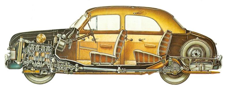
overdrive if any) and the final drive or axle gearing, there was in the majority of front-engined rear-driven cars a propeller shaft, familiarly known as the prop-shaft and once dignified by the name of its inventor, Cardan.
In essentials it was a simple tubular shaft (a solid one would be heavier and too likely to bend) incorporating some form of universal joint at each end, permitting relative movement between the gearbox - which usually rocked with the engine on flexible bearers - and the rear axle, which may move up and down on its springs. If the rear suspension was independent, the final drive gears would be housed in a case fixed to the chassis, and relative movement would be comparatively slight.
The Live Axle
The movement of a live axle was much more demanding, as the angular displacement of the shaft was accompanied by a variation in the distance between its extremities, and some form of telescoping joint was necessary to provide for this. A splined slip joint was usual, but the splines tended to bind when subjected to really high torque, and high-powered cars sometimes had to have a more expensive form of slip joint in which ball bearings were interposed. A drive shaft with a universal joint at only one end created problems of variable angular velocity of rotation. One with universals at both ends created problems of whirl, and it was also difficult to balance.
A common counter-measure was to make the prop-shaft in two parts, with the central joint (another universal) supported by a flexibly mounted steady bearing. Another albeit more expensive way was to put the gearbox at the mid-point, as was done in the Morgan, but the space it occupied was seldom to be spared. Cars with independent rear suspension were sometimes arranged with the gearbox at the rear, perhaps in unit with the final-drive casing, in the interests of mass distribution: this created its own problems, as the rotational inertia of the prop-shaft was added to that of all the other rotating portions of the gearbox and clutch that have to be slowed or accelerated by the
synchromesh mechanism during gear-changing.
In any case the prop-shaft was problematic, which is one of the reasons
front wheel drive or rear engine location was preferred by some manufacturers. If in either of these cases the engine was set with its crankshaft, the final reduction gearing from the gearbox output shaft to the axle shafts could be by cylindrical gears, either straight-cut or of helical tooth formation. Otherwise the drive line would have to be turned through 90° by bevel or worm gearing, which was more expensive to produce and less easy to accommodate. The choice of gearing may be determined by the displacement (if any) between the axes of the input and output shafts: if there was no displacement the bevel gears may be straight-toothed for efficiency or of spiral form for quietness, if there is a slight displacement the hypoid bevel will be necessary, and if it is larger then the designer must resort to worm gearing, which sometimes creates problems in lubrication.
The Differential
Differential gearing is surprisingly simple in construction, and normally effective in performance, usually consisting of two inward-facing bevel sun gears linked by a cluster of two or more bevel planetaries, although spur-gear differentials have been extensively used in the past, as in the
Austin 7. Cars with more power than traction or suspension control often need a self-locking differential to avoid the inconvenience resulting from excessive wheel-spin, and if it is thought necessary this can be embodied in one of its three currently popular forms, all of which rely upon friction to make the differential deliberately inefficient. That leaves the half-shafts, which finally communicate torque to the hubs of the driving wheels. If those wheels are independently suspended, the half-shafts will be beset by the same problems of articulation as the prop-shaft of a live-axle car, with the design of the universal joints complicated in the case of
front wheel drive cars by the need for the wheels to be turned for steering.
The Half Shafts
If the half-shafts are enclosed in a live rear axle, they are simple enough, but care still has to be taken in their design because the torque they transmit is greater than that passed by any other component in the transmission system. Every gear reduction produces torque multiplication, and by the time that the rotation of the engine's crankshaft has been reduced through a bottom gear which may be as low as 4:1 and again through the final-drive gearing which may be of similar magnitude, the half-shaft will be turning at a sixteenth or less of the rate of the crankshaft. Even allowing for all the mechanical losses on the way, the multiplication of torque would be of a similar order - and although a conventional differential would divide that torque equally between the two half-shafts, a self-locking one may act to pass all or most of it through one whenever the
tyre on the other loses its grip. It is little wonder that a broken half-shaft was for a long time the most common transmission failure - and remains arguably the biggest mechanical problem a classic car owner will encounter.
Also see: Transmission Repair |
Automatic Transmission |
The History of the Transmission and Driveline