Clutch problems can be caused by a variety of faults, and the cure varies from the easier clutch adjustment to the harder clutch overhaul. DIY will save you a great deal in service costs and ensures a thorough job. The clutch is the first stage in the transmission of power from the engine to the final drive mechanism. It forms a link between the engine and the gearbox. Since it must transmit the full torque of the engine against the complete weight of the car, it is liable to wear and need repair and replacement. The symptoms of faulty clutch problems basically fall into four categories:
- Snatch
- Excessive slippage and drag
- Judder or take-up faults
- Squeak
A common cause of snatch, (where the clutch takes effect suddenly instead of smoothly sliding into operation), can be a distortion of the clutch plate due to overheating. To establish this as the fault, you should first check that the engine and gearbox mounts, the sub-frame attachments, the prop-shaft and the rear axle are all securely attached to their various points. If these elements are at all loose, the excess freedom of movement will cause resistance to smooth clutch engagement. If this check finds nothing wrong you can be sure that clutch plate distortion is the problem, and should consider an overhaul to exchange the buckled parts for new ones.
Excessive slippage or drag (where the gearbox becomes stiff or the car tries to creep when held in gear with the clutch pedal on the floor) very often indicates maladjustment of the operating mechanism or faulty hydraulics. To check for drag, have the car at rest with the engine running and engage first gear. Then, without letting the pedal off the floor, select neutral followed by first again. If there is any resistance at all to the second engagement of first gear, clutch drag is present and the operating mechanism should be adjusted as described below. If resetting the adjustment makes no improvement, overhaul is the only course of action. Judder or take-up trouble can be caused by the faults that cause snatch, or maladjustment. Squeal can be caused by faulty linings, or a worn or dry release bearing.
Clutch Adjustment
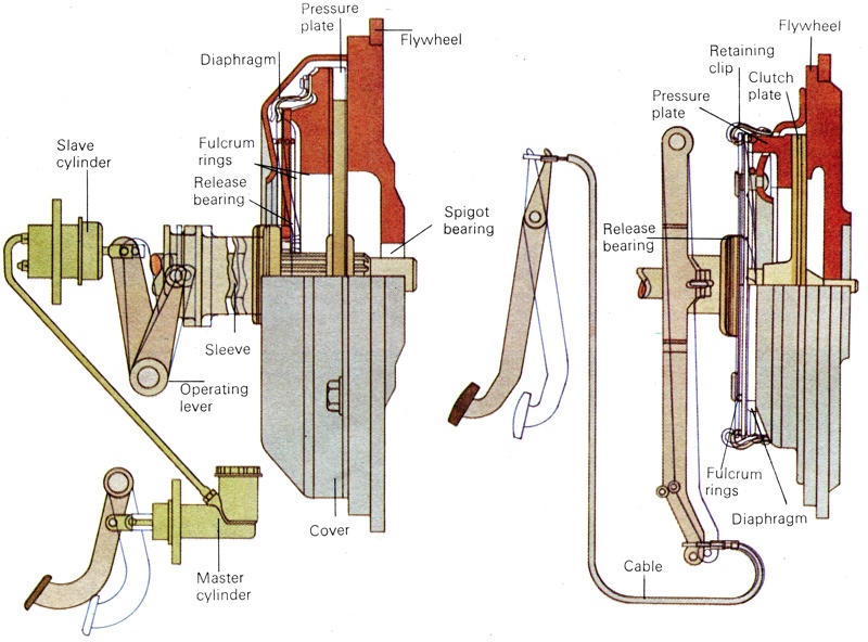
Many clutch problems are caused by maladjustment. As the clutch wears, the free play (essential in both cable and hydraulic operating mechanisms to allow the full spring pressure to be exerted) will decrease. If this free play decreases too much, the condition will be reached where the engagement does not fully release, causing drag and a stiffness of gear change. If the adjustment is set correctly, the centre plate of the clutch should disconnect completely before the pedal is floored and there should be a small amount of noticeable free play at the top of the pedal movement. This free play is normally specified as about 6 mm (0.25in.) at the release lever end of the system, or about 20 mm (0.75in.) at the pedal. Adjusting the mechanism should be carried out at the release lever end of the cable system, or at the slave cylinder piston rod in hydraulic systems. Some hydraulic systems are self-compensating and have no provision for adjusting the free play.
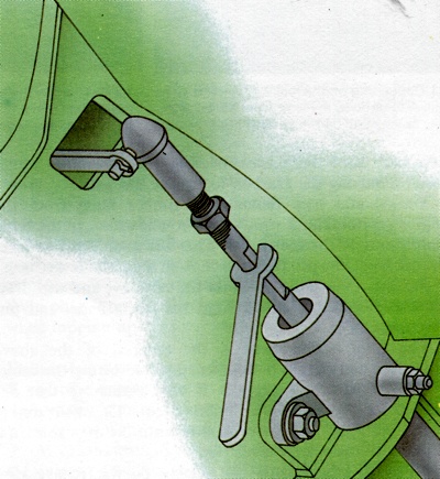
In the hydraulic clutch system, slacken the lock nut with two spanners, then turn the adjusting screw.
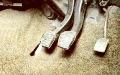
In cable operated clutch systems, the brake and clutch pedals should be at the same height. A simple inspection will show if adjustment is needed - as is the case in the photo above. |
Hydraulic System Adjustments
With the hydraulic system, the adjustment is usually provided at the slave cylinder with a screw and lock nut on the pushrod. You should slacken the lock nut using two spanners, and screw the operating ball nut a few turns. Now check the free play and, when correct, retighten the lock nut. When air enters the hydraulic system, the fluid becomes partially compressible and the clutch will not free completely. Pumping the pedal is a temporary cure, but the permanent solution lies in bleeding the system and checking for leaks. To do this, first top-up the reservoir and make sure that it never empties during the bleeding process.
Next, you should remove any floor covering which might restrict the full pedal travel, carefully wipe away any road dirt from the bleed nipple located on the slave cylinder and attach a rubber tube to this bleed nipple. You should then immerse the other end of the tube into a clean glass containing a little hydraulic fluid. Hydraulic fluid is very corrosive to paintwork and a great deal of care should be taken in handling it. Next, slacken the bleed nipple by half to one third of a turn, then have a friend push the pedal slowly to the floor and give it several short, sharp jabs, followed by another long full stroke while you check the fluid being expelled into the glass for bubbles of air. Finally, have the friend slide their foot off the pedal sideways, to allow the pedal to spring back sharply. This procedure should be repeated until clear, air-free fluid is being pumped into the glass jar, then retighten the nipple in the middle of a full stroke. Remove the rubber tube and jar, top up the reservoir to the correct level, clean round the neck and replace the cap. If the system fails to improve with bleeding, a defective cylinder seal is indicated.
Cable System Adjustments
The main problems arising with a cable system are liable to be due to maladjustment from either clutch wear or cable stretch, or from partial or complete parting of the strands forming the cable. If the clutch action is very stiff, first check that the cable has not been displaced. It should take up a smoothly curved arc between the pedal and the release lever without any sharp kinks and, if possible, it should not bend back upon itself in an 'S' shape. If the clutch cable strands have partially or completely separated, the only answer is to remove the cable and fit a new one. The new cable will usually have shaped ends which prevent the inner cable from being withdrawn, but during manufacture the unit will have been thoroughly lubricated to protect the strands from wear.
To remove the cable, first you should detach the clutch cable support bracket on the clutch bell housing and swing it aside. Next slacken the clutch cable adjuster nut and lock nut, peel back the rubber gaiter and pull the clutch inner cable from its fixing. Utmost care should be taken during this operation, for the release arm should not be moved more than 12.75 mm (,0.25in.) or the arm may become detached from the release bearing retainer. This would mean removing the gearbox to replace the arm. You should now remove the rubber bung from the engine rear bulkhead which will provide access to the cable connection on the foot pedal. This will enable you to lever the cable eye and pin from the clips on the pedal lever.
Finally, remove the pin from the cable eye and withdraw the clutch cable assembly from the fascia panel and put this to one side. The cable replacement is the reversal of the above procedure and should be followed by readjusting the cable. The adjustment procedure is very similar to that described for the hydraulic clutch system. The main difference is that the screw and lock nut are on the cable end, adjacent to the release lever. When all adjustments and checks do not relieve slip, judder, squeak, drag or snatch, the clutch unit itself must be removed for attention. If this is the case you should be prepared to devote a weekend to the job.
Clutch Removal
If you have reached the stage where an overhaul cannot be avoided, never buy replacement parts until you have stripped out the old parts. This is because there are three elements which are always available separately, and they may not all need replacement. Procedures for clutch overhaul differ considerably according to the mechanical layout of the engine and transmission in the car. This chapter will deal with the conventional front-engine layout as used in the Ford range (excluding Fiesta), Morris Marina, Vauxhalls and similar cars. In the majority of front-engined rear-wheel drive cars, the gearbox can be removed and the clutch serviced without removing the engine.
A careful study of the access to the transmission bell housing retaining bolts will be a good indication as to whether the gearbox can be separated without removing the engine. If you have enough room to operate your spanners satisfactorily and there appears to be enough clearance to ease the gearbox back at least 50 mm (2in.) when everything is disconnected, the job should be started by jacking up the rear of the car and mounting the axle on securely positioned stands. This is assuming no hoist or pit are available. An alternative is to drive the car up on ramps at the rear. Having carried out one of these procedures, chock the front wheels securely to prevent the car from moving forward.
Place the gear lever in neutral and remove the carpets or any console from the transmission tunnel inside the car, then remove any rubber gaiter that may be fitted. Most gear levers are attached to the top of the transmission housing by a domed screw cap or a flange held down by set bolts. If you cannot turn the domed cap by hand after you have pressed any locking tabs up flat, and no spanner is available, or there is insufficient access for a proper grip, it can be sometimes loosened by a sharp tap with a blunt chisel. You should take care not to damage the cap. Before proceeding any further, where possible drain the oil from the gearbox. To do this you should undo the gearbox drain plug and then drain the oil into a clean container. When all the oil has drained out, replace the drain plug. The oil collected in the container can be reused when topping up.
Exhaust System Removal
With some engine layouts, it may be necessary to remove the exhaust system before being able to reach the clutch plate mechanism (for example, this will be necessary with the Morris Marina). If this is the case you should disconnect the exhaust downpipe from the manifold and either remove the pipe or reposition it out of the way by wiring it to some part of the structure. It will also be necessary to remove the speedometer cable. To do this you should detach the speedometer cable cir-clip, knurled nut, or single bolt and withdraw the assembly. If an automatic reversing light is fitted, you should disconnect it by pulling the plug off the switch in the side of the gearbox.
Starter Motor Removal
You should now disconnect the main battery cable and remove the starter motor. To remove the starter motor, first disconnect the starter motor cable from the terminal on the starter motor end cover. Next, undo and remove the nuts, bolts and spring washers which secure the starter motor to the clutch and flywheel housing. Then lift the starter motor away by manipulating the drive gear out of the ring gear area and then from the engine compartment.
Drive Shaft Removal
The next step is to remove the drive shaft (propeller shaft). You should first mark the rear axle flange with a file to allow you to reassemble it in the same position to maintain balance. If the car has universal joints at each end of the shaft, undo three of the four bolts at either joint, then, with an assistant supporting the weight of the shaft, undo the remaining two bolts and withdraw the unit. If the drive shaft is fitted with a centre bearing, you should detach this bearing's housing from the reinforcement in the floor before loosening each end. Some cars have one universal joint between the drive shaft and the differential, and a sliding splined joint at the gearbox end. This has no flange, but simply pushes into the gearbox tail housing. Pull the drive shaft rearwards to disengage the splines. Finally, seal the gearbox extension housing with a plastic cap or polythene bag held by a rubber band. This will prevent any residue oil from draining out as the gearbox is tilted backwards.
Clutch Disconnection
With a cable operated clutch, you should next slacken off the adjustment, as described before, sufficiently to allow you to remove the cable end from the release lever. With hydraulic operation, you should seal the vent hole in the reservoir with non-porous sticky tape to prevent the loss of hydraulic fluid. Then, either detach the slave cylinder completely from the release lever and the transmission housing, or detach the hydraulic pipe from the slave cylinder. With self-adjusting hydraulic systems, you should use wire or string to prevent the piston rod from being pushed by the spring inside the cylinder.
The next stage is to undo the bolts connecting the bell-housing to the engine block. Some cars use two or three nuts at the top of the bell-housing, and there are usually dowels as well. The final step is to remove the gearbox mounting. Before you undo the bolts, pass a rope around the tail housing and up into the car through the gearlever hole in the floor. As you release the bolts, you should have an assistant take the weight of the unit by keeping the rope taut. Ease the unit backwards to disengage the input shaft splines from the clutch centre plate, then lower it.
Clutch Assembly Removal
The engine flywheel will now be revealed with the clutch assembly attached to it by a ring of six or eight bolts. All that remains to be done is to remove the actual clutch assembly. To do this, slacken each of the retaining bolts a little in turn. The clutch springs will tend to force the cover off as these bolts are released, and the clutch assembly will come away in two parts. You will now be able to see the state of the linings, the presence of any distortion or contamination of the centre plate, and the condition of the thrust race. The thrust race will have been removed with the release lever as part of the gearbox assembly.
Replacement clutch parts are available as three separate elements: a pressure plate; a driven plate; and the release bearings. It is worth considering the work involved in getting access to the clutch before skimping on the extent of the overhaul. Clutch parts wear together, so it is false economy to replace only one part, such as the driven plate, as the other parts will soon wear out.
Clutch Re-Assembly
If the flywheel has been badly scored, it may be necessary to fit a new one and in this case you should always use new locking tabs for the retaining bolts. Examine the spigot bearing in the flywheel centre. If it is worn, replace it, otherwise smear with HMP grease. If the flywheel is in good condition, clean it thoroughly with methylated spirits, and in either case you should clean the face of the new pressure plate in this way. Next, lightly grease the splines in the centre plate and position the centre plate with the protruding side away from the flywheel. To do this you will need to borrow or make a special aligning tool because if the centre plate is not perfectly central the gearbox will not mate with the engine without distorting the centre plate. The aligning tool, which can be made quite quickly in wood, consists of a two-diameter mandrel. The tool's smallest diameter must be a snug fit in the flywheel spigot bearing and the larger diameter must be a similarly snug fit inside the centre plate splines.
The centre plate assembly should be offered up to the flywheel and, having done this, you should start all the retaining bolts in their threaded holes. Then, position the aligning tool and continue to tighten the cover plate bolts in turn by small amounts to compress the clutch springs gradually. When you have tightened them all completely, you can remove the aligning tool. The next step is to replace the gearbox. This can be a tricky job due to its weight. First lightly grease the input shaft splines, then check to see if there is a blank spline which should correctly align with the clutch centre plate splines. Make sure you never let the shaft take the weight of the gearbox, then gently ease the unit home. Never attempt to force it into position.
Now refit the cross-member and the bell-housing bolts, then reconnect the speedometer, the reversing light lead if fitted, and the clutch operating mechanism. Once you have done this, remove the tape previously placed over the reservoir vent (if you have a hydraulic system), and bleed the system. Before replacing the drive shaft, check the free play of the system and adjust it to the correct amount, refit the starter motor and reconnect the battery lead. You can now replace the drive shaft. To do this, align the file marks made on the rear flange and fit new self-locking nuts. Finally, reconnect the exhaust system and refit the gear lever and interior trim. Lower the car to the ground and test the clutch. The new clutch linings may require a short time to bed in and once they have, the adjustment may need resetting.