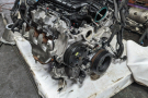
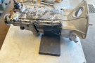
Getting maximum performance and economy from every gallon of petrol you buy depends to a large extent on an efficient and well-tuned carburettor. Carburettor overhaul is rarely specified as part of a car's normal service schedule, but the enthusiastic owner will find that regular stripping, cleaning and adjustment pays dividends. The SU carburettor is fitted to a vast number of older classic British cars and light vans, since SU-Butec was a subsidiary company of
British Leyland. Probably the most successful constant depression (variable jet) type of carburettor in use during the 1970s, the SU had changed little in basic design over the years.
The only exception was the HIF type, designed expressly to comply with increasingly strict emission control stand-dards. Not only were these somewhat different in design; sometimes they were also made tamper-proof. The "conventional" SU was an exceptionally long-lived and durable instrument. It has the twin advantages of comparatively simple construction and relatively large bearing areas for its moving parts. In addition, overhaul is quite straight-forward. Properly looked after, the carburettor should never wear out and will probably outlive the vehicle to which it is fitted.
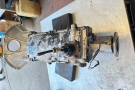
The most common variety of SU prior to the HIF series was the HS type. The procedure for dismantling and overhaul given here is based on the HS design, but the earlier models differ little and can be dealt with in largely the same way. The only significant difference between early and late models is in the construction of the float assembly. The older carburettors are fitted with adjustable brass floats and pivots. These were superseded by nylon floats with brass pivots and finally by all-nylon floats with moulded pivots which do not allow for adjustment. Before any serious work can be done on the carburettor it must be removed from the car; the worst enemy of the carburettor is dirt.
Removing The Carburettor
Before you can remove the carburettor you must first take off the air cleaner, then disconnect the fuel feed pipe which will be secured by some form of screw clip and pull off the engine breather and vacuum advance pipes if your car has them. Undo the connections to the throttle cable or rods and the choke cable and remove the throttle return spring. With all the attachments free, the nuts securing the carburettor to the inlet manifold can be removed. The carburettor can then be lifted clear of the car. If there are any gaskets under the carburettor, buy replacements and be sure to fit them on re-assembly.
Dismantling The Piston
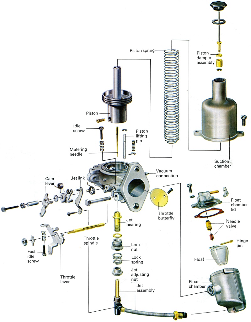
The first step when dismantling and overhauling an SU is to remove and check the piston assembly. The SU, like other constant depression carburettors, relies for efficient operation on the smooth passage of the piston up and down in its suction chamber. It is, therefore, vitally important that all dirt is removed from the carburettor before you start to dismantle it. Special carburettor cleaners are available which are specially formulated to remove any dirt from the inside of the unit. The outside can simply be brushed clean with petrol or engine cleaning fluid.
With the exterior of the carburettor clean, unscrew the damper rod. Remove it, then drain out the oil by inverting the unit. Next undo the two, three or four screws which secure the bell-shaped suction chamber. On the smaller carburettors you should mark the position of the chamber relative to the main body before removing it so that it can be replaced the same way round on re-assembly. The larger units fit only one way so there is no need to mark them. If the suction chamber sticks rotate it slightly to free it. Then lift it straight up. Do not tilt it to one side during removal or you will bend the metering needle. The piston and spring will now be accessible and both may be removed simply by lifting them clear. Once again take care not to damage the metering needle.
SU springs are usually colour-coded by means of paint marks near one end of the coils. Take this opportunity to check that your spring corresponds to that specified by the vehicle manufacturer and if you renew the spring be sure to buy the correct replacement. Next check the condition of the piston rim and the internal bore of the suction chamber. If there is any dirt present remove it. A fairly accurate test for piston bore wear is as follows. First block the transfer hole or holes in the piston base. Lightly oil the outside of the piston rod and the suction chamber bore and push the piston home in the chamber, omitting the spring but with the damper assembly fitted. Turn the assembly the right way up. It should take about six seconds for the piston to drop out.
Obviously you should not allow the piston to fall to the ground when carrying out this check, particularly if the metering needle is still in place. Too heavy an oil, or dirt, may result in the piston sticking. Too fast a drop points to excessive wear and you will need to renew both chamber and piston. Next the needle should be examined for signs of wear. Vertical score lines on one side are the most common sign. They show that the needle has been rubbing too hard against the side of the jet. Check also for signs of jet ovality. Only severe ovality will be visible to the naked eye, so if the unit has been in service for some time it is good policy to replace the needle and jet whether any wear is evident or not. As the needle and jet wear together always replace them as a pair, never one or the other.
Older SUs had a rigidly held needle, but all recent models have sprung or "biased" needles. In these the needle has a small amount of side force constantly applied to it by a small spring, which allows for a more consistent fuel flow. To remove the needle in either case slacken the small grub screw in the side of the piston and slide out the needle. If the needle sticks try tapping it gently inwards before again trying to pull it out. Unless it is to be renewed take great care not to bend or scratch the needle. If the needle is to be scrapped and a new one installed, retain the tensioning spring and carrier collar, as these will not be supplied with the new needle.
Dismantling The Float Chamber
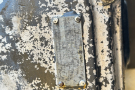
Once you have overhauled the piston assembly you should next dismantle and service the float chamber and the components inside it. The float chamber is the cylindrical attachment on one side of the carburettor body. Remove its cover by undoing the three retaining screws. Under one of these screws you will find an identification tag which will have the carburettor's reference number on it. Quote this number when buying any replacement parts. The float and needle valve assembly is located on the underside of the float chamber cover. All modern float assemblies are plastic and no adjustment of float height is possible. If the float is faulty it should be replaced. On older models however the float pivot arm is brass and float adjustment is possible. Using a 3 to 5 mm (to 3/16ins) round bar such as a screwdriver shaft or drill bit, place the bar across the centre of the float chamber lid, parallel with the hinge pin.
The face of the float lever should just rest on the bar when the needle is on its seating under the weight of the float. If it is not correct, adjust it by bending the hinge gently closer to the hinge pin. To remove the float simply push out the hinge pin from its non-serrated end using a small nail or similar item as a drift. The float should then be checked for punctures and dents. If the float is punctured or has a dent in it, it will not correctly regulate the fuel flow. When you remove the float the needle from the needle valve is likely to fall out, so take care not to drop it. If it does not fall out remove it and inspect the needle point for wear, which usually takes the form of ridging. If wear is evident renew the needle and its seating. The seating can simply be unscrewed, preferably using a box spanner of 8.58 mm (0.338ins) across the flats.
Dismantling The Jet Linkage
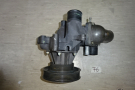
The next part of the carburettor to service is the jet linkage. The main jet unit is tensioned upwards by the choke linkage. The choke enriches the mixture simply by moving the jet downwards to a thinner section of the metering needle, so allowing more fuel through. The jet is linked to the base of the float chamber by a fuel supply pipe. Start to dismantle by undoing the self-tapping screw which connects the jet to the choke mechanism, while taking the tension off the jet. Next disconnect the pipe from the float chamber, taking care not to kink the pipe, which can split the inner plastic tube. The jet can now be withdrawn from the carburettor body. If the metering needle is found to be worn then the jet also will be worn and should be replaced. A wide variety of jets is available, so it is advisable to take the old one with you to the spares' supplier.
Jet identification is by means of coloured bands round the supply tube - but if your carburettor is old these will probably have disappeared. The jet adjusting nut, spring, locking nut and bearing may all be removed from the carburettor body and examined. They are not normally subjected to much wear, so little is likely to be wrong with them. The main check is for free movement of the adjustment nut, as adjustment will be difficult if it is at all tight on its threads. Also, while the jet is accessible it is wise to remove it and clean the threads. Replacement seals and washers for the jet assembly should be obtainable and it is a good idea to fit them. There is little point in dismantling the choke linkage and the only parts likely to need replacing are the return springs and it will be obvious if they are missing or broken.
Dismantling The Throttle Butterfly
Look now at the throttle butterfly and spindle. Open the butterfly by hand and feel for any sideplay on the spindle. If play can be felt, mark one edge of the butterfly and the adjacent part of the carburettor flange to facilitate correct re-assembly, then squeeze together the splayed ends of the split screws securing the butterfly to the spindle. Remove these screws then the butterfly can be eased out. Next, remove the spindle nut after first knocking back its retaining tab washer. Note the location of the throttle lever in relation to the spindle and carburettor body and take off the lever and washer. The spindle can then be withdrawn. Fortunately, with the SU, wear usually takes place on the spindle more than in the bearings in the carburettor casting, so usually a new spindle will cure any slackness. If the wear is in the bearings, the carburettor may still be serviceable if you can find a carburettor reconditioning specialist who can re-bush the spindle.
Final Checks
Lastly, you should look at the damper rod unit although there is little likelihood of problems there. The small washer which sits on the damper bush must have its chamfered edge upwards and the vent hole in the cap must be clear. Other than that, the assembly must simply be kept clean. Thorough cleaning of the carburettor and float chamber internal surfaces is all that remains before commencing re-assembly. As with the exterior, intensive treatment with clean petrol or degreasing fluid should be adequate. Pay special attention to removing the deposits which will have built up in the sludge traps situated in the float chamber base each side of the main fuel outlet.
Re-Assembly
Start re-assembling the carburettor by putting the throttle assembly back together. Fit the spindle into its bearings, hold it in the wide open position and slot the butterfly into place�lining up your scribe marks. With the throttle now closed, loosely install new split screws. Ensure that the spindle shoulder projects beyond the body and fit the washer, lever, nut and new tab washer. Tighten both the spindle nut and the butterfly securing screws progressively - snapping the throttle open and shut a few times to ensure that everything aligns properly and is not going to jam up. Finally, lock the spindle nut with the tab and open out the split screw ends just enough to stop them turning.
Next, re-assemble the float chamber components. Install the needle valve seating in the cover. Do not overtighten it. Then insert the needle, point first. Replace the float and gently press in the hinge pin. If it is an old brass unit, check the float level as described above. Re-fit the cover using a new gasket and tighten the screws uniformly and progressively. Do not forget the identification tag. Now turn to the piston assembly and re-fit the metering needle - ensuring that the locking screw tightens on the flat machined on the needle guide. Carefully fit the piston and needle assembly into the body, engaging the piston keyway over the key in the body and replace the spring. Lightly oil the suction chamber and, with your marks aligned, screw it back in position. As you do this check that the piston does not become trapped. If it does become trapped it must be released.
Screw the jet adjustment nut up to the maximum weakness position - that is, as high as possible - then slide the jet into place and hold it right in. Check whether the piston still moves freely. If you did not disturb the jet bearing and locking nut it should do so but if it tends to stick you will have to centralize the jet.
Centralizing The Jet
To centralize the jet, first remove it from the carburettor. Then take off the jet adjusting nut and remove the spring. Now screw up the adjusting nut, minus the spring, as far as you can without forcing it. Slacken off the locking nut until it can be turned using only your fingers. Next, press down on the piston rod, via the top of the suction chamber, so that the metering needle taper forces the jet into a central position. Then tighten the lock nut. Check that the piston still moves freely by lifting it and letting it fall. It should hit the jet bridge with a soft metallic click. Now lower the adjusting nut and check again that the piston is free to move. The centralizing process must be repeated from the beginning if the metallic click is not the same with the adjuster nut in both positions.
With the jet satisfactorily centralized re-fit the adjuster spring and connect the jet supply pipe to the base of the float chamber. A new seal will be required if the old jet was retained and the tube should project at least 5 mm beyond the seal. As an arbitrary setting, to enable you to start the engine prior to fine adjustment when the carburettor is installed, position the jet adjuster two complete turns down then re-connect the choke mechanism. Fit the carburettor back on to the inlet manifold and re-connect the various linkages and pipes. Fill the damper with 20W50 grade oil to about 13 mm above the top of the moving guide rod. The carburettor is now ready for final adjustment.
Mixture And Idle Adjustments
Before you adjust any carburettor you should be sure that the valve clearances and engine timing are correct. The principal adjustment on an SU are as follows. With the engine warm and running turn the jet adjusting nut and listen for an improvement in the sound of the
engine, this will be when the engine ceases to hunt or sound "throaty" but ticks over smoothly. Once you think you have found the correct mixture setting, raise the piston using the lifting pin. If the speed of the engine rises the mixture is too rich; if it falls, then the mixture is too weak. Aim to find an adjuster nut position between these two extremes, at which lifting the piston causes a momentary rise in the speed of the engine followed by a return to normal idling speed.
Once you have found the correct mixture setting you may find that this has raised the idle speed. If so, re-adjust the idle speed of the engine so that it settles at about 800 rpm. This is achieved by turning the throttle speed screw. The final task in this carburettor overhaul is to set the fast idle. To set the fast idle pull out the choke control on the dashboard until the linkage is just about to move the jet. Then turn the fast idle screw until the correct engine speed of around 1200 rpm is achieved. At this number of revs any ignition lights inside the car will go out. The carburettor service is now complete.
Also see: Pre-War American Carburettor Maintenance