Cylinder Head
The Cylinder Head is an iron or light-alloy casting which fits tightly to the cylinder block and contains the combustion chambers, valves, valve seatings and spark-plugs. An efficient
cylinder head will improve performance more than would be expected by many people. With no moving parts other than the
valves, the cylinder head is involved in all aspects of a four stroke engine's operation - induction, compression, ignition, and
exhaust. One way of improving a
cylinder head is called porting and polishing. This very time consuming process enlarges and maximises the finish of the intake and
exhaust ports, and allows a more efficient flow of gas. Big
valves and multi-valve heads are also beneficial as they improve swirl patterns of the fuel/air mixture in the combustion chamber and thereby increase the amount of fuel that is burnt and turned into horsepower. A head can also be shaved — that is, a few thousandths of an inch of metal are scraped from the head surface to reduce the space in the compression chamber, raising the compression ratio and power in most cases.
Cylinder heads can also be fitted with roller rockers. Roller rockers take the place of the standard cast iron rockers which transfer the movements of the camshaft, through the pushrods, to the
valves (in an overhead valve engine). When the camshaft lobe lifts a pushrod, the rocker is forced to rock — hence the name — and open a valve. Cast iron rockers, while cheap to manufacture, have inherent problems. They are prone to breakage during extended periods of high engine speeds. They also scrape across the valve tip during the opening process, a method which causes a great deal of friction, heat, and can shorten the lifespan of
valves and valve guides. Roller rockers, on the other hand, actually have a roller bearing in their tip, which rolls across the valve tip, drastically reducing friction.
OHV vs. Side Valve Engine
When it comes to older style engines there are two main types, the O.H.V. and the side-valve engine. Portage problems on an O.H.V. engine are quite different from those on a side-valve, owing to the ability of the side-valve head to create natural turbulence, whereas a hemispherical O.H.V. head depends entirely on inlet port velocity for its turbulence; therefore the inlet port on a suitably designed side-valve can be somewhat larger.
Checking for Warpage
With the cylinder head on the bench, the first thing to do is remove all carbon and make a thorough examination of the head for possible warpage. To check that the machined gasket area is true, the correct way is to put the head on a surface plate; but, since the average owner will not have a surface plate, a good straight-edge will serve the purpose. An accurate metal straight-edge should be placed over the surfaces of the block and the head. This will give you a rough idea as to any possible warpage. The head and block faces should then be lapped together by means of grinding abrasive; this will immediately show up any high spots. To get rid of these high spots, continue lapping until you achieve a nice grey matt surface all over. This procedure, incidentally, will be applicable to both O.H.V. and side-valve cylinder heads.
Another thing common to both the O.H.V. and the side-valve is the question of compression ratio. The fundamental way of increasing power output is to increase compression ratio. It can be done very simply by machining the cylinder-head face. If it is desired to increase the compression ratio, this machining should, of course, be done before the lapping for correct sealing.
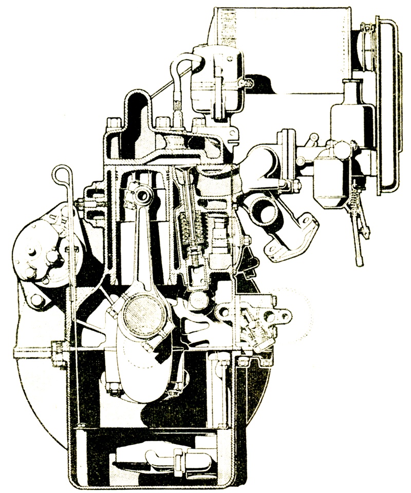
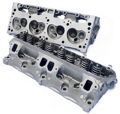
An example of a turbulent-type cylinder head, where attention has been given to the smallest details. Ports are polished, plug threads blend perfectly into the combustion chamber. The valve-line is streamlined to encourage gas flow.
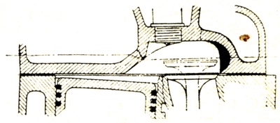
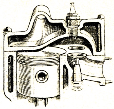
In some older engines it is advisable to relieve part of the head next to each inlet valve by grinding off the portion shown in black.
|
Combustion Chambers
The combustion chambers inside the cylinder head should be polished all over, and any rough casting marks should be removed. This is necessary because a highly polished finish will not only delay carbon formation, but, more importantly, will greatly assist the turbulence and gas flow of the mixture, which are so essential to good combustion. Now a set of dummy or old spark plugs should be screwed into the cylinder head and observed as to whether any thread in the plug sockets remains visible. Any such thread should be removed with a rotary file, since it might be a possible source of pre-ignition. Particular attention should be paid to the area of the head adjacent to each inlet valve. Performance will be further improved if the area adjacent to the valve is relieved by grinding to improve the gas flow, or '"breathing," of the engine.
Compression Ratio
Compression ratio is largely a matter of the tuner's personal preference. With special fuels the compression-ratio limit for the side-valve is about 9 to 1 without detonation. With pump fuel, the limit depends to a great extent on the design of the cylinder head, but most side-valve engines would take a compression ratio of 7 to 1 on standard fuel. To work out the compression ratio of an engine, the following method is recommended:
With the piston at top dead centre and the valves in closed position, a quantity of thick grease should first of all be pushed down round the edge of the piston and cylinder bore in order to make it temporarily fluid-tight. All surplus grease should be wiped away. As a further precaution, put a small quantity of grease on the valve seatings, too.
The cylinder head is now placed in position on the block and is tightened down. A burette graduated in cubic centimetres is obtained and is filled with a light mixture of kerosene and engine oil; the mixture is then transferred from the burette through the plug aperture of one cylinder, to a level reaching where the bottom of the plug comes. This will give you the volume of the combustion chamber in c.c. Next figure wanted is the volume of the cylinder bore displaced by the piston in its up-and-down movement. This is obtained, of course, by dividing the cubic capacity of the engine by the number of cylinders. The formula for wprking out the compression ratio is then as follows:
Compression ratio equals swept volume of cylinder bore, plus volume of combustion chamber, the whole divided by volume of combustion chamber.
In order to get rid of the fluid from the combustion chamber, the cylinder head must be dismantled. Each cylinder should be checked in this manner individually; and, in view of the fact that we have tried to balance all our reciprocating masses, it is surely sensible to try to ensure that the compression ratio of each cylinder is equal. Otherwise it is not difficult to see that, if we are running very close to the detonation margin in so far as the fuel is concerned, it will be quite easy to have one cylinder practically detonating the whole time if its ratio happens to be appreciably higher than the rest.
In one engine that I had to deal with many years ago, we were continually troubled with extreme roughness when running on a certain ïalcohol fuel. A check-up demonstrated that a difference in combustion-chamber volume of only 2 c.c. made a difference as between 10 to 1 compression ratio and 13.5 to 1. If, after increasing the compression ratio, you find that the cylinders are not all equal, you will have to equalise them by grinding the inside of the combustion chambers. The higher ratios must be brought down to equal the lowest. If the general result is then not high enough, further metal must be machined off the head face.
The Exhaust Port
Now we come to the subject of ports, valves and manifolds. Since the exhaust port is, in my opinion, one of the most important parts of the engine, I will deal with it first. Contrary to many popular 'deas, the exhaust port should be considered as part of the tract extending from the valve right through the system, until the expanding charge is finally exhausted into the atmosphere. The port, in other words, should be thought of as a system including the silencer, the length of the exhaust pipe, and its diameter.
It must be remembered that, when the exhaust valve begins to open, the piston is at the lower part of its stroke and the burning gas as such has a relatively small inherent velocity. In fact, common timing practice indicates an exhaust valve opening of somewhere in the region of 55 deg. before b.d.c., which means that the piston is still travelling downwards. As the valve continues to open and the piston accelerates after b.d.c., the velocity of the gas increases in relation to the piston travel, plus the natural expansion ratio of the burning charge. This charge, which is at an extremely elevated temperature, can be very destructive to the exhaust valve itself.
Therefore, the first principle is to keep plenty of exhaust-valve guide round the valve stem in order to protect the stem. Do not make the mistake of cutting the valve guide back in order to obtain greater exhaust-port area. However, the exhaust tract should be made as smooth and free from obstructions as reasonably possible by polishing. The guide may be streamlined and the port size blended carefully to the manifold size, since it is most important that gases are not trapped by overlapping where the manifold butts to the cylinder block. Where standard manifolds are being used, it is sometimes possible to open the exhaust port by about l/16in. in order to give the gas a freer flow into the manifold. It must be remembered, however, that it is bad practice to make a very large port under the valve and then restrict the port area at some later point in the system. The gases are expanding the whole time, and you should strive to keep them moving as rapidly as possible to obtain what is called a good extractor effect.
Too large an exhaust system can, once again contrary to popular belief, be quite detrimental to good exhaust flow; if the gases expand too rapidly before they reach the atmosphere, they will lose extractor effect ó which in turn will react seriously against the engine's "breathing" ability. Another point is that a very large valve port, particularly beneath the valve seating, will tend to raise exhaust-valve temperatureóa most undesirable feature. Therefore, be very careful with the use- of the port grinder.
Exhaust Manifold
The next objective is the exhaust manifold: unless you are prepared to go to the expense of having a special exhaust-pipe system made up, you can only make sure that the best possible alignment is maintained wherever pipe flanges butt each other. Having seen instances of enthusiasts fitting flexible exhaust piping, a note of warning here. A little mature consideration will quickly show that, although you may have spent hours polishing your exhaust ports, all that good can be undone by the great internal resistance offered to the rapidly travelling gases when they flow over what can best be described as an old-fashioned scrubbing board.
The Inlet Port
The inlet port system really comprises all that area extending from the carburettor intake to the valve. And how many instances have I seen of even racing engines with beautifully finished inlet tracts and ports all nullified by some great obstruction such as the side of a bonnet placed quite close to the carburettor intake! But we will assume that you have not made this mistake, and that maximum freedom of entry is given to the carburettor intake in your layout. Let us now follow the rapidly moving charge through the carburettor body. First obvious point of interest is the spot where the carburettor bolts to the manifold.
Make sure that the carburettor body does blend with the manifold in diameter, and that the gasket does not overhang the joint. The manifold itself should be given particular attention: sudden changes in diameter are the greatest evil and should be avoided where possible. The manifold will eventually strike the port where it butts on to the block face. Here there are usually gaskets, made of copper or similar material. Be sureómost sureóof the mating of the port here.
Next step, of course, is the inlet port itself, which should be one of the most carefully studied parts of the engine. The valve guide should be removed and the port highly polished. Particular attention should lae paid to the underside of the valve seating in the matter of polish; but, before polishing here, it is suggested that an old valve be taken and the head reduced in diameter until it will just enter the port throat. This valve should then be used as a template for all the inlet valve seat-ings, so diameters are uniform. We have endeavored by mechanical means to ensure that our compression ratios are equal. If, therefore, you consider normal manifolding, the apparent distribution difficulties become clear, particularly where what are known as "siamesed" inlet ports are usedói.e., where one branch of the manifold feeds two inlet valves.
In view of these difficulties, which are usually insoluble other than by fitting individual carburettors, we must take every precaution to ensure that equal charges are aspirated as far as reasonably possible, by closely watching and equalising inlet port diameters. Next step in relation to the inlet port is to assemble the inlet valve on to its seating without a spring; any sharp restrictions round the valve must be religiously removed.
A final point on the inlet port: only take the smallest amount from the inlet port itself when grinding and polishing the port, since countless fine engines have been ruined by taking as little as l/16in. of metal from this area. The reason is that the diameter of the inlet port not only affects the "breathing" capacity of the engine (or what is more technically described as volumetric efficiency) but also, most important, it is intimately tied up with the question of gas turbulence within the combustion chamber itself. All the filling in the world is of little use if the necessary turbulence is lacking. Making the inlet port too large will ruin engine performance. As regards the valves, these should be ground-in accurately and highly polished all over.