Universal Joint
A component that is used on driveshafts that allows a rotational movement but can move up and down to allow for
suspension travel. In order to transmit power at an angle and also to take care of the continual up-and-down motion of the propeller shaft, one or more flexible connections, known as universal joints, are used between the transmission and the rear axle. A universal joint is a flexible connection to carry motion from one rotating shaft to another. It is so designed that it can automatically adjust itself to transfer power through various angles. The wrist is a familiar example of the principle of the universal joint, since it can bend up and down and in all directions and still be used to deliver twisting force. There are a number of different types of construction used to obtain the universal joint effect, but the basic principle is the same for all. This simple type consists of a yoke attached to each shaft. The yokes, In turn, are fastened to a crosspiece.
The automobile's propeller shaft always has one universal joint, and can have two, between the transmission and the axle so that the up-and-down movement of the rear end will not affect the driving power of the shaft. Now the front unit of the car is coupled to the rear unit by a flexible connection that permits the power to flow continuously from the engine to the rear wheels and turn them. The turning rear wheels develop traction on the road. In a strict sense, traction refers to the friction developed between a powered surface and the surface in contact with it. In the case of the automobile, therelore, traction is the resistance to slipping - or push - developed at the point of contact of the driven rear wheel with the surface of the road on which it rolls. There are two ways of applying the traction - or push - developed by the rear wheels on the road, back to the car to propel the car forward. They are called:
- The Hotchkiss Drive.
- The Torque Tube Drive.
In the Hotchkiss drive, the rear-axle housing is firmly bolted to two springs. The forward end of each spring is secured in a bracket mounted to the side frame of the car. The rear end of each of these springs is shackled so that it will be free to move. In the Hotchkiss drive, as the rear wheels are turned and the car is pushed forward, the actual pushing is performed through the springs. In other words, the springs absorb the strain of the pushing action of the wheels. Therefore, in a Hotchkiss system, the drive comes to the car's frame in back of the middle section. Two universal joints are generally used to provide the necessary flexibility for the propeller shaft in the Hotchkiss drive system. In the torque Tube drive, one end of a strong tube is bolted to the forward part of the rear-axle housing. The propeller shaft operates inside the torque tube.
The forward end of the torque tube is mounted with a universal ball joint. This joint allows no forward and back movement of the tube�and yet it can move up and down with the propeller shaft. In this type of drive, when the wheels rotate the axle is pushed ahead, propelling the torque tube forward. The tube forces the transmission case and the engine ahead. Since the engine is bolted into the car's frame, the engine takes the thrust and transmits it to the frame. Thus, in the torque tube drive, the drive comes to the car's frame at the forward end - instead of in back of the middle section as it does in the Hotchkiss drive. Both these types of car drive are used in the industry - each having certain advantages.

A: Drive Shaft, differential end. B: Drive Shaft, Wheel enclosed. C: Centre Ball, differential side. D: Centre Ball Pin, wheel end. E: Driving Balls.
|
How To Maintain And Replace A Bendix Universal Joint
The diversity of the Willys Overland pre-war, war-time and post-war models calls for some specialised service data. This procedure for Bendix Universals is applicable to many other makes too. Some models have a Rzeppa universal joint and a different procedure must be followed.
Firstly remove the axle shaft assembly and begin dismantling the universal unit by the following method:
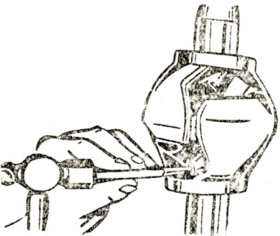
- By using a pin punch and hammer, drive out the retainer pin which locks the centre ball pin at the wheel end of the shaft (Fig. A) and bounce end of shaft on a block of wood to cause centre ball pin to move into drilled passage on the shaft.
- Pull the two halves apart and bend sharply. Rotate centre ball until grooved sides line up with the ball raceway. This will permit the adjacent ball to be moved past the centre ball and be removed from the joint. Remaining three balls and centre ball will then drop out.
Inspect all parts thoroughly. If raceways are worn, install a complete new axle shaft and joint. If centre pin is worn, it should be replaced. Replace worn, pitted or scored balls. Original diameter is .875 in. (22.2 mm) but replacement balls are available from .003 (.76 mm) oversize to .003 in. (.76 mm) undersize in' steps of .001 in. (.25 mm), to permit selective fits. When replacing balls, measure old balls with micrometer and start reassembly with balls of the same size.
If considerable play is present, use balls one size larger and recheck for play. If play is still present, use still larger size balls. In final assembly, the two largest diameter balls should be placed diagonally across from each other. Selective assembly is not necessary when installing a new centre ball or centre ball pin.
To Re-Assemble Bendix Joints
- Place differential half of axle shaft in a vice, with machined portion above jaws of vice and install the centre ball (with the hole drilled in it) in the socket of the shaft, with the hole and groove facing you.
- Drop centre ball pin into the drilled passage in the wheel half of shaft. Then, place the wheel half of the shaft on the centre ball and slip the three balls into the raceway.
With the Bendix universal joint, install drive flange on axle splines without shims. Install two flange screws and draw up snug, but not tight. Install axle nut and draw up snug. With a feeler gauge, measure space between the outer end of the wheel hub and the inner face of the drive flange. The distance measured with the feeler gauge plus .015-.035 in. (.38 to .89 mm) is the required clearance at this point. If no clearance is found with the feeler gauge, install a .010 in. (.25 mm) shim between the driving flange and the hub. After the proper shims have been installed, replace driving flange on splined shaft and install the six retaining screws.
After the axle is completely assembled, recheck to make certain that the proper end-float has been established. Back off axle nut so that a .050 in. (1.27 mm) feeler gauge will go between nut and driving flange. Tap end of shaft with a lead hammer and shaft will move the amount of end-float. If space is less than .015 in. (.38 mm) add to thickness of shims; if more than .035 in. (.89 mm) remove correct number of shims.