Introduction
Some of the toughest engineering problems in the development of the automobile have stemmed from the fact that an
internal combustion engine can only function over a relatively narrow speed range and cannot produce torque when the output shaft is stalled - such as can be done with a
steam engine or gas turbine. Thus a clutch and torque-multiplying
transmission is needed to achieve acceptable road performance. Converting the
transmission output into torque at the two rear wheels also requires some sort of bevel drive, differential gear and universal joints. All these drive-line problems together have occupied the auto industry since its beginnings.
Planetary Transmissions
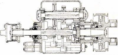
It is not generally realized that some of the earliest cars had planetary transmissions. (This is where a central sun gear, outer ring gear, and several planet gears on a planet carrier meshing between the sun and ring gear transmit the torque. By locking one of the elements, and driving one of the other two, various gear ratios are achieved.) The principles of the planetary gearset were well understood in the late 1800s. This type of transmission was adapted to the use of simple band-type clutches for changing gears smoothly - which was a definite problem on early-day cars. It is well known that the
Ford Model T, the car that literally put America on wheels, used a simple 2-speed planetary transmission with multi-disc starting clutch up until the mid-'20s. This was a fairly reliable and efficient way to handle the gear-changing problem on early cars, although it did make a rather complex and expensive transmission.
The first sliding-gear
transmission was seen on the French
Panhard-Levassor in the mid-1890s. The output here was on the secondary, or countershaft, so all the forward gears were indirect. The three gears were engaged progressively at consecutive notches on the gear lever. The driver had to go through all three gears when starting from rest. The new transmission was simpler, cheaper and more rugged than existing planetary types—but there was a problem of gear clashing on shifting, tremendous gear whine with the straight cut spur gears and the indirect drive on top gear gave additional friction losses.
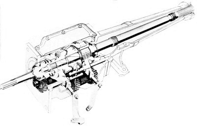
Section of the typical 3-speed sliding spur gear of the early 1900s. Note the sliding dog at right end for direct engagement of top gear.
Two speed planetary box of the Model T Ford. A multi-disc clutch started the car from rest, while band-type clutches were used to control planetaries.
Cone clutch of the early 1900s. The layout gave wedging action which absorbed high torque capacity.
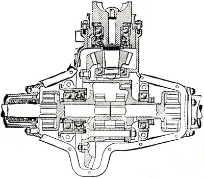
Bevel gear rear end and arched axle of 1913 Peerless. This used spur gear differential and pot-type U-joints to give angle drive which was a popular feature of the period.
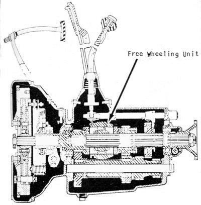
Studebakers free wheeling unit of 1931. Roller-type overrunning clutch on mainshaft allowed the car to coast when the throttle was off.
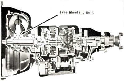
The Free-Wheeling-Unit was later adopted for use in automatic transmissions, such as this 1956 torque converter type from Borg-Warner. Free-wheeling units lost favour because of a lack of braking on downgrades.
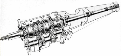
Warner Gear T-10 4-speed transmission that became popular in the late 1950s and early 1960s. It had been re-tooled from a 20 year old design, and featured synchromesh on all four gears.
Ford's all-synchro 3-speed was one of the few new transmission designs of the mid 1960s. |
The Dog Clutch
This last problem was solved before 1900 by using a dog clutch to connect the clutch shaft (input) to the transmission main-shaft on top gear. This put the drive straight through and left the gears free-wheeling. The move cut down the noise as well as the friction in top gear. This was the breakthrough that sold the sliding-gear
transmission to the auto industry. It gave the early engineers a relatively simple torque-multiplying device that was quite light and compact (much more so than earlier planetary and indirect sliding-gear types), cheap to manufacture, quite efficient and reasonably reliable and long-lived. Life and reliability were quickly improved by developments in ball bearings and metallurgy. As a matter of fact, students of technical history have said that transmission requirements did more to force metallurgical developments than any other area of car design. This period saw the early development of nickel, chrome and vanadium steel alloys, as well as case-hardening and oil quenching.
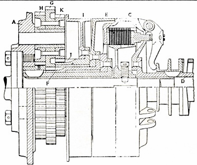
The Cone Clutch
The cone-type clutch with leather friction facings was widely used on early cars. This type of clutch has conical facings that come together with a wedging action. Tremendous torque capacity with a given diameter and engaging force can be obtained. For example, with an average 12° cone angle, every 100 lb. of axial engaging force gives 480 lb. of outward pressure against the friction facings. The cone clutch had an inherently vicious action, too - it grabbed and jerked when it was engaged.
This drew more than a few customer complaints 60 years ago, but there was a blessing: There was relatively little slip to heat up and burn the friction facings. That was one of the bigger problems with early clutch design. There just wasn't any efficient friction materials that would take any sort of punishment. Leather proved to be one of the best for cone clutches but it certainly left a lot to be desired. But the fact that there was little slip with this type of clutch gave pretty good results all around.
The lack of good friction materials also led to the development of multi-disc clutches with metallic friction facings running in oil. By distributing the friction and heat load over a larger area with multiple discs, and using oil to absorb heat and smooth the engaging action, automotive engineers got fairly good performance and long life, although at a sacrifice in cost.
It wasn't until around 1920 that woven asbestos-base friction materials became available to make practical the single-plate clutch that is in universal use today. It's the simplest and cheapest layout known and yet has smooth engagement, good torque capacity in relation to diameter (because of the high friction coefficient of the asbestos-base material) and reasonably long life under normal conditions. There have been relatively few changes in clutch design in the last 40 years.
Rear Axle Design
Rear axle design progressed swiftly in the early 1900s. The first cars used chain drive but this was on the way out after the turn of the century. The general rear end layout known today— bevel gear drive from a front engine and transmission, with integral gear differential—was well established by 1905. Differentials were either of the bevel or spur-gear type. Both operated on the same principle. The spur-gear type was probably cheaper to manufacture in those days but it required more space for a given torque capacity, so was soon dropped out of the picture.
A breakthrough came in 1912 when Packard adopted spiral bevel gears for its rear axles. This would be equivalent to going from spur to helical gears with a straight gearset. Gears are much quieter because the teeth engage and disengage gradually and smoothly, instead of with a sudden pounding action as with spur gears. Helical gears had begun to show up in transmissions before 1910, with excellent results in noise reduction. (Generally, the helicals were used on the top two ratios only.) Packard's switch to spiral bevel gears in its rear axle set a pattern that the whole industry copied within a few years.
Early universal and slip joints were crude by today's standards. The earliest cars used "pot" type joints for both actions. This is nothing more than a square block with rounded sides (in an axial direction) that slides in a corresponding square socket. It is free to swivel and slide as it turns. It had lots of friction and wear, but it worked. The Cardan-type U-joint, with cross and yoke, came into use in the early 1900s. Use of bronze bushings for the swivelling surfaces cut down friction and wear. The pot joint continued in use for slip joints through 1920. Splined slip joints and needle-bearing Cardan U-joints came into general use very gradually in the '20s and '30s. And, of course, the trend today is toward double Cardan U-joints, to cancel out the pulsating rotational motion that is inherent with this type of joint.
Hypoid Rear Axle Gears
Two revolutionary developments came close together in the 1927-1928 period. One was hypoid rear axle gears and the other was the
synchromesh transmission. "Hypoid" gears, in effect, are spiral bevel gears with the pinion gear displaced below the centerline of the ring gear. The pitch surfaces of the gear teeth are curved like a hyperboloid of revolution - hence the name. The whole purpose was merely to drop the driveshaft one or two inches and allow a lower floor in the body. (It was about this time that the stylists were getting busy in Detroit and there was much pressure on engineering for a lower chassis.)
Hypoid gears were actually developed by engineers at the Gleason Gear Works in Rochester, N.Y. - the same people who developed spiral bevel gears in 1912 - and again it was
Packard that had the vision to go out on a limb with them. There was a definite
lubrication problem with the early hypoids because of the substantial sliding motion between contacting gear teeth. This required special extreme-pressure lubricants and these were just in their infancy in the late 1920s. Owners and mechanics had to use just the right lubricant or the rear end was gone in a few miles. It took nerve for
Packard to risk this just to drop the driveshaft an inch or so, but the gamble paid off and hypoid rear end gears swept the industry in a few years.
Synchromesh Transmission
General Motors made the breakthrough on
synchromesh transmissions. It introduced the feature on the 1928
Cadillac. Up to that time,
gear shifting with a sliding-gear
transmission was a real headache. There was no way to shift without clashing the gears unless a double-clutching technique was used to equalize the speeds of meshing gears, or unless the driver waited a second or two between shifts to speed up the engine and let the gears equalize themselves.
The mark of the expert driver was their smooth, quiet shifts. GM's early
synchromesh mechanism utilized bronze-faced cone clutches to equalize gear speeds. One side of the cone was integral with the gear, and the other was in a stamped steel drum that was splined to a sliding member with a dog clutch on the end to engage a corresponding clutch on the gear. The components were positioned in such a way that the cone clutch came into engagement just before the dog teeth engaged, to bring the speed of the gear up or down to the speed of the sliding member.
Thus the dog clutch would engage without any clashing and the second and third speed gears were in constant mesh. It was the same principle of modern synchromesh mechanisms, though a little more crude and less durable under hard shifting conditions. As today, the synchromesh feature was provided only on the top two ratios, with low ratio still a sliding gear. It was felt that low gear would only be used from a standing start, so no synchro mechanism was needed there. (
Packard brought out a 3-speed gearbox in the late 1930s with
synchromesh on all three ratios and
Ford tooled up such a transmission in
1963. Otherwise the standard 3-speed manual
transmission on American passenger cars had always used synchromesh on only the top two ratios.)
Free-Wheeling Transmissions
During the late 1920s and early 1930s there was also a brief flurry of interest in 4-speed and free-wheeling transmissions. The free-wheeling mechanisms used a simple overrunning clutch (roller type) to prevent feed-back of torque from the back wheels to the engine, so the car would coast when the throttle was released. The clutch was mounted on the back of the transmission and could be cut in or out via a control lever on the dash. The feature was boomed as a gas-saving feature at the time. But safety authorities looked down on it because of the lack of engine braking on downgrades. Freewheeling
transmissions quietly faded from the scene in the late 1930s.
The 4-speed flurry was another thing. Many Detroit engineers wanted to use lower axle ratios to get better highway fuel mileage and quieter, smoother cruising. But with the existing 3-speed
transmissions there wasn't enough overall torque multiplication in low gear for acceptable getaway. Also, the acceleration in the 40-60 mph speed range would be soft with the faster ratio, since the big ratio gap between second and third didn't permit second gear to be used for highway passing (not to mention the fact that nobody wanted to shift those sliding gears more than was absolutely necessary). They felt the answer might be a 4-speed transmission with closer ratios, in conjunction with a faster axle ratio.
Franklin, Graham, Kissel, Stutz, Packard, Gardner and Peerless
The
Chrysler cars of the 1930 period were a good example of this thinking. A 3-speed was used on the lighter models, with ratios of 3.11 and 1.69 in low and second, respectively, with 4.70:1 axle gears. On the heavier models a new 4-speed was used, with ratios of 3.38, 2.35 and 1.41 on the lower three gears, in conjunction with 3.82 axle gears. This gave very good getaway in low gear, good cruising with the 3.82 axle gears, and the close synchromesh third permitted use of this gear (5.4 overall ratio) for passing on the highway.
It worked out pretty well. Other makes using 4-speed transmissions during this period included
Franklin,
Graham, Kissel,
Stutz,
Packard, Gardner and
Peerless. Some 4-speed
transmissions evolved to an
overdrive fourth gear in the main gearbox, with direct drive on third, and the original slow axle ratio was retained. This was never satisfactory because the indirect drive in fourth was noisy and wasted power.
This led naturally to the famous Borg-Warner overdrive transmission, introduced on the 1934
Chryslers. Essentially, a planetary overdrive gear was tacked on the back of a more-or-less conventional 3-speed
transmission, which stepped up the speed of the driveshaft (in relation to engine speed) about 30%. This proved to be a much better answer than the overdrive 4-speed unit, and it eventually became quite popular on American cars. After this there really wasn't a lot more vital technical development on manual transmissions on American cars. Steering column
gearshift levers came in in the late 1930s, and there was some interest in vacuum-assisted clutches and shifting mechanisms (though nothing much came of the latter).
And the advent of the GM Hydra-Matic transmission in 1940 quickly put a stop to heavy engineering development of the manual gearboxes. Visionary Detroit managers could see the potential of the fully-automatic fluid-drive transmission for American passenger cars and they could see no good reason for spending millions on new manual gearboxes that they felt were doomed to a declining market. As a matter of fact, many of the manual gearbox designs used during the 1960s were actually tooled before 1940. The later all-synchromesh 3 and 4-speed floor-shift sports-type transmissions were about the only exciting things that happened in this field during the next 30 years. Only by the 1990s did things start to change.
Also see: Transmission Repair |
Automatic Transmission |
How It Works - The Transmission