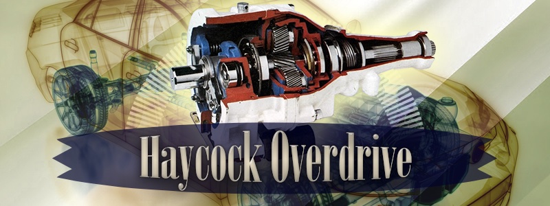
The Laycock Overdrive Principal
We won't spend time explaining the benefits of an overdrive unit on this page, suffice to say that has been covered in our "
how it works: the overdrive" and our "
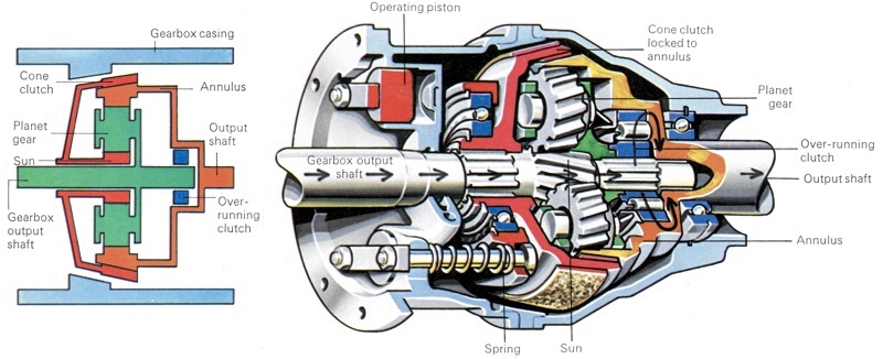
auto definitions: overdrive" sections. In the Laycock overdrive unit, the annulus was mounted on the output shaft of the unit and drove the propeller shaft and the planet carrier was splined on to the output shaft of the main gearbox. The sun gear was mounted on a sleeve which slid over the gearbox output shaft and splined to the sun gear was a cone clutch. The cone clutch was used to engage or disengage the overdrive.
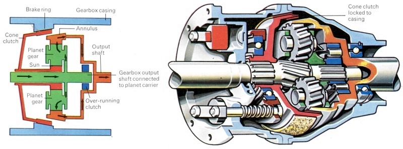
This cone clutch had friction linings on both the inside and the outside faces to that it could lock on to either the conical outside surface of the annulus or a similarly-shaped brake ring mounted in the overdrive casing. When locked to the annulus the cone clutch rendered the gear train inoperative and the whole assembly rotated as a single unit, giving normal direct drive from the gearbox. However, when the cone clutch was locked to the overdrive casing, its splines would hold the sun gear stationary and the overdrive would come into operation. When the overdrive was disengaged, the cone clutch was held in the position by springs and when the overdrive switch was moved to the engaged portion, the movement caused hydraulic pistons to push the cone clutch backwards until the clutch locked with the casing.
The last major component was the over-running clutch which connected the mainshaft from the gearbox to the main output shaft. These shafts were directly coupled when the car was in normal drive, yet the output shaft was able to rotate faster than the gearbox shaft when overdrive was engaged. This was achieved by the simple free-wheel mechanism of the over-running clutch. The clutch itself had three main components - inner and outer races and a set of rollers.
The inner race was connected to the gearbox mainshaft and had a set of shallow lobes or cams around it. The outer race was attached to the output shaft of the overdrive, which had a plain bore. This then fitted over the inner race, with the rollers, one for each cam, in between. When the gearbox shaft began to turn, the rollers in the inner race would run up the side of the cams and wedge against the outer race, thus creating a solid drive. But when overdrive was engaged and the output shaft was driven by the annulus, its greater speed forced the rollers back down and into depressions between the cams, thus disconnecting the drive. The output shaft could, therefore, turn at a higher speed while the gearbox mainshaft maintained its previous rate of rotation.
A further function of the over-running clutch was to ensure that drive was maintained while overdrive was being selected. If it were not fitted there would be a temporary loss of drive when changing from direct drive to overdrive and the driver would, therefore, have to release the accelerator pedal during engagement of overdrive.
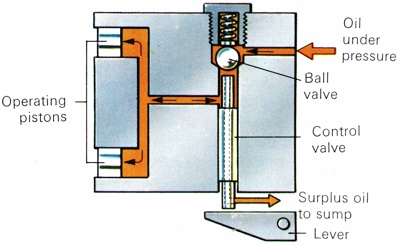
Laycock Overdrive A and D Type cone clutch, which was operated by hydraulic pressure. Pressurized oil is fed to the positions when the solenoid lifts a lever and raises the control and ball valves.
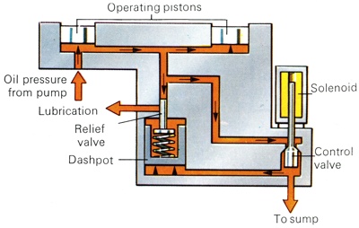
Laycock Overdrive J Type. In this case, a solenoid opens a valve which allows oil under the releif valves dashpot. This raises the pressure in the circuit and forces the operating pistons down their bores. |
Laycock Control Mechanism
When the driver operated the overdrive switch on the gear lever or the steering column they brought two control mechanisms (one electrical, the other hydraulic) into operation. First of all, the switch completed an electrical circuit to a solenoid, which caused a plunger in the overdrive unit to move. The movement of the plunger opened a mechanical valve which allowed oil pressure to reach the hydraulic operating pistons. The pistons were then forced forward by the oil pressure and their movement pushed the cone clutch so that it locked to the casing and brought in the overdrive.
The hydraulic pressure required to operate the pistons for the cone clutch was supplied by an oil pump and used the gearbox oil. The oil pump was operated by a cam lobe mounted on the gearbox mainshaft. The Laycock hydraulic system and the solenoid circuit varied slightly according to the overdrive model type and its applications. The earlier A and D-type overdrives were used on large-engined and small-engined cars respectively but were very similar. The later J-type overdrive, however, used a different hydraulic control and solenoid.
Laycock A and D-Type Control System
The solenoid in the Laycock A and D-type overdrives had two windings, one which drew a large current of 17 amps and was used to "pull-in" the solenoid plunger and another which drew a smaller lamp current and was used to "hold-in" the plunger while the overdrive was in operation. The "pull-in" winding was switched off by a pair of contacts in the back of the solenoid once it had moved the solenoid plunger into position. The solenoid operated a lever which moved the control valve.
When overdrive was selected the control valve was lifted and moved a ball valve off its seat. This allowed oil pressure from a hydraulic accumulator on the A-type or from a pressure relief valve on the D-type to reach the cone clutch operating pistons. When direct drive was engaged the current to the solenoid was cut off, so the solenoid released its pressure on the lever. The spring-loaded valve, therefore, re-asserted its pressure on the control valve and closed the oil pressure port. Then, as the control valve moved away from the ball-valve, a hole down the centre of the control valve was uncovered and this allowed oil pressure from the piston to be exhausted into the gearbox sump.
Laycock J-Type Control System
The solenoid for this overdrive unit had only one winding which drew about 2 amps and the solenoid plunger acted directly on the control valve. When the
transmission was in direct drive, oil was pumped past the crowns of the operating pistons to a relief valve. The relief valve lifted at a low pressure, about 2.1 Kg/cm2 (30psi) and channeled the oil back to the gearbox sump. When overdrive was selected the solenoid opened the control valve. This movement of the valve opened one port but closed another that lead to the sump. The open port allowed oil to reach the bottom of a dashpot underneath the relief valve.
The dashpot piston was then pushed up against the relief valve spring and this increased the pressure at which the relief valve would operate to about 35.2 Kg/cm2 (500psi). This meant that the oil pressure in the operating piston circuit would rise and move the pistons. These then operated the cone clutch. When direct drive was re-selected the control valve closed and, re-opening the sump port, released the oil pressure in the dashpot allowing the relief valve to open and reduce the pressure in the operating piston circuit. The J-type system was considered to be an improvement on the earlier designs because it allowed for a more controlled build-up and release of pressure, which in turn gave smoother engagement and disengagement of the overdrive.
Laycock Electrical Control Circuit
The full electrical circuit consisted of the driver's selector switch, the overdrive relay, the solenoid and the gearbox inhibitor switch. When the overdrive switch was operated the relay contacts closed and switched electrical power to the overdrive solenoid. This would, however, only happen if the inhibitor switch in the gearbox selector mechanism was closed because the electrical supply to the relay came via this switch. With this type of circuit, once the selector was in the overdrive position the transmission would stay in overdrive whenever top gear and, if applicable, third gear, were selected. If the driver changed down into second or first gear the inhibitor switch would break the circuit and the transmission would revert to direct drive but as soon as third or top gears were selected again the transmission moved back into overdrive unless the switch position had been altered.
However, some cars with Laycock overdrive have a self-cancelling switch circuit which allows the overdrive to be automatically cancelled once second or first gears are selected. This type of switch is steering column-mounted and is spring-loaded into the central position. To select overdrive the switch is pushed down and then released and after this movement it returns to the central position. This switch is used in conjunction with a double-contact relay, in which, once one pair of contacts have been closed by the switch operation, they are held closed by the electrical circuit fed through the second pair of contacts. When the main electrical feed is broken by the inhibitor switch both sets of contacts open and stay open.
With this type of circuit if the driver has selected overdrive in third gear and then changes into second, the overdrive will be cancelled and when third gear is next selected it will be direct third, not overdrive third. If overdrive is then required it will have to be re-selected.
Laycock Developments
Laycock Engineering Ltd. developed an overdrive system for automatic transmissions during the early 1980s. The company fitted a standard overdrive to the automatic gearbox on a 3-litre
Ford Granada. The conversion was reported to have given an 18 to 20 per cent reduction in
engine speed and an improvement of at least 11% in fuel consumption. Laycock used a number of sensing and inhibiting switches such as a top gear switch, a speed switch and a manifold vacuum switch, to ensure that overdrive was only engaged in top gear at a speed at which there would not be excessive torque converter slip.
Also see: How It Works - The Overdrive |
Borg Warner Overdrive |
Overdrive Definition