Hubb Van Doorne
Nearly all of the automatic transmissions discussed here at
Unique Cars and Parts refer to gearboxes with two, three or four ratios. These generally tended to have fewer ratios than their manual equivalents because of the torque converter's ability to multiply the engine's torque, so enabling the engine to pull sufficiently strongly over a wide speed range. Things have changed these days, with automatics having as many, or more, gears than the equivalent manual transmission. While many of the problems with automatics have now been overcome, wind the clock back and there were limits to what a torque converter could do and the transmission designer faced the problem of matching the available gear ratios to the needs of the car as best they could.
This would be altogether different if the transmission itself could set up whatever gear ratio was needed. The engine could then be matched to the speed of the car so that it was giving the best possible performance or, alternatively, the best possible fuel economy, all of the time. To obtain the best possible acceleration from a standing start or when overtaking, the engine needs to be kept at its peak torque speed; for greatest economy to be obtained it needs to be kept at the speed at which its fuel consumption is best for that particular throttle opening. In practice, it would not have been too difficult to arrange the governing of the engine to ensure that it maintained peak torque. Achieving the best possible fuel consumption, however, would have required that the transmission be able to match the engine's actual condition with a range of fuel consumption values over a range of speeds and throttle openings. If this was to be done to the best advantage, it demanded electronically-operated controls.
Before the advantage of electronics, one simple but effective design was the DAF-designed Variomatic transmission, designed and developed by Hubb Van Doorne, which was also used in the smaller Volvo models, the 66 and 343. Like all such transmissions, the Variomatic was a CVT (continuously variable transmission). Its principles of operation showed how infinitely-variable gearing (within certain limits) could be achieved, while its drawbacks explained why so much development work was necessary to make CVTs a reality today.
Variomatic Belt Drive
The heart of the Variomatic system was a pair of belts which transmitted the drive from one pair of pulleys to another pair. Changes in the gear ratio were obtained by varying the operative diameter of the pulleys. The Variomatic transmission had six major components: two driving pulleys, two driven pulleys and a pair of driving belts to link them. The driving pulleys were mounted on a cross-shaft, which was turned by the engine and the driven pulleys were positioned and held on shafts in the final drive assembly. The transmission provided an almost infinite range of ratios by automatically varying the operative diameter of the pulleys. When the car was pulling away from rest the engine's torque needed to be considerably multiplied - in other words the engine had to turn faster than the car's wheels. Therefore, the driving pulleys needed to have a small diameter, while that of the driven pulleys had to be large.
When the car was underway there was less necessity to multiply the engine's torque, so if the driving pulley's diameter could be made to expand and the driven pulley's diameter to contract, an efficient ratio for the new condition would result. A logical extension of this concept was to very gradually change the pulley diameters as the car pulled away. This resulted in a "stepless" or continuously variable gearbox. This was achieved by the Variomatic.
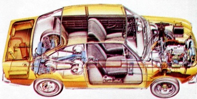
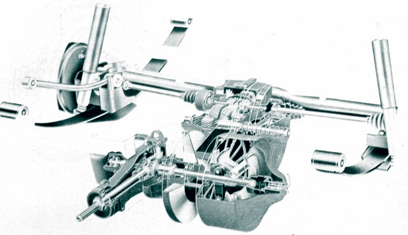
Volvo released the above cutaway to promote one of the advantages of the Variomatic Transmission - much better weight distribution.
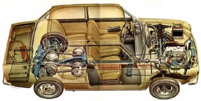
Another cutaway, this time showing the DAF 55.
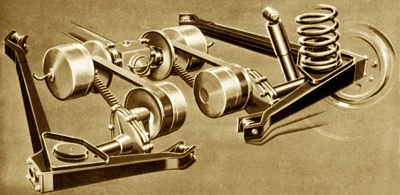
Variomatic Transmission as used in the Volvo 340 and Volvo 360. |
Varying The Pulley Diameters
It is not true to say the Variomatic's pulleys changed in diameter overall. In actual fact they remained a constant size and it was the portion of the pulleys that the belts actually operated upon that varied in diameter. This resulted from both the construction of the pulleys and the shape of the belts. Each of the pulleys was made in two halves. One half was fixed to its shaft, while the other was free to slide along it. The face of each half was conical, so that when viewed across their axes the space between a pair formed a deep "V".
The belts themselves had a slight wedge-shaped section and therefore fitted neatly into the space between the pulley halves. When the pulley halves were close together the belt would seat itself near the pulley's outer edge. But, if the sliding half then moved away, the "V" of the pulley would widen, the belt would slide deeper into it and the effective diameter of the pulley would have been reduced. Therefore, when the car needed a considerable torque reduction the halves of the driving pulleys would be well apart and the belts would thus operate upon a small diameter.
The halves of the driven pulleys, meanwhile, would be close together, so the belts would engage a large diameter. As the car gathered speed the driving pulleys would close up and the driven pulleys open and the transmission ratio would change. The theory was simple enough but the practical details of how the sliding portions of the pulleys were compelled to move in and out were more complex. The sliding section of each driving pulley was a loose fit on the cross-shaft.
One part of the sliding section took the form of a hollow drum assembly and within this drum were a set of centrifugal weights - these weights were pivoted on the cross-shaft. Once the car had pulled away from rest it was necessary to make an upward gear change, this being effected by moving the sliding portion of the driving pulley in towards the fixed half, so enlarging the pulley's effective diameter. The movement was achieved by the centrifugal weights. As the car gathered speed these weights were thrown outwards by centrifugal force and contacted the sliding half of the pulley assembly. Their pressure forced it along the cross-shaft, closer to the fixed portion of the pulley. The driving belt was then squeezed up into a higher section of the driving pulley's "V", so that the effective diameter of the pulley was enlarged and an upward "gear change" was made.
When the average car climbs a long hill a downward gear change is normally required. With the Variomatic this meant that the sliding portion of the driving belt pulley needed to be pushed back along the cross-shaft. When a hill was encountered the car's resistance to forward movement would obviously increase and this would be transferred to the transmission through the driving wheels. The resistance on the wheels increases the force on the driving belts and these consequently wedge down in the driving pulleys, thus forcing them apart. This compelled the belts to operate on a smaller driving pulley diameter and the transmission therefore "changed down" to a lower ratio.
How The Driven Pulley Expands And Contracts
How the driven pulley expands and contracts is a comparatively simple operation because the driven pulley merely responds to the change in working diameter of the driving pulley. As the driving belt is of a fixed length, when an upward change was made and the driving pulley expanded, the belt would tighten around the driven pulley. The belt would therefore force itself deeper into the "V" of the driven pulley, so pushing both of the halves apart. Conversely, when the driving pulley contracted, there was a certain amount of slack in the belt and, as the driven pulley was spring-loaded, the two pulley halves were forced back together, consequently obliging the belt to engage a larger effective diameter. The belts and centrifugal weights were assisted in changing the transmission ratio by a control vacuum from the inlet manifold of the engine. The drum on the sliding pulley was divided into two chambers by a diaphragm, which formed a flexible air-tight seal. Its centre was attached to the transmission cross-shaft, while its perimeter was linked to the walls of the drum. Each half of the drum was connected, by pipes, to the engine's inlet manifold.
If the air within either side of the drum was sucked out by the vacuum in the inlet manifold the atmospheric pressure on the other half of the drum would cause the entire sliding pulley to move along the cross-shaft. While the car was being driven away from rest, vacuum was admitted into the drum's outer chamber. Air pressure in the inner chamber therefore forced the sliding portion of the pulley along the cross-shaft, thus squeezing the belt on to a larger working diameter and helping the transmission to "change up". The vacuum control was therefore assisting the centrifugal weights, which, in these circumstances, were already sliding the pulley in the same direction. Now, with the car underway, sudden acceleration may be needed for overtaking. Most automatic transmissions, the Variomatic included, have a kick-down control that will immediately supply a lower ratio in these circumstances. The driver merely presses hard on the accelerator and the lower ratio is provided automatically.
In the case of the Variomatic, sudden depression of the accelerator released the vacuum from the outer drum. This removed the assistance given to the centrifugal weights, and the sliding half of the pulley therefore moved away from the fixed half, consequently forcing the belt to run on a comparatively smaller pulley radius. The vacuum inlet positions were reversed, however, when the car was descending a steep hill, and a low gear was required to provide engine braking. In these circumstances, the driver would lift their foot from the throttle, and vacuum would then be admitted to the inner chamber of the drum. Atmospheric pressure in the outer chamber then helped to pull the sliding pulley away from the fixed portion, against the force of the centrifugal weights. Forcing the halves of the pulley apart would cause the belt to run on a smaller driving pulley radius - in other words, a lower ratio will then be provided.
The vacuum was channelled to the correct chamber portion of the drum by a valve (or valves). On the DAF 33 and 44 models this valve was operated by the throttle linkage to the carburettor - when the driver moved the accelerator they also adjusted the position of the valve. From the model 55 onwards, DAF employed a slightly more sophisticated valve that had a solenoid triggered by an engine speed sensor. The Volvo 66 and 343 models refined the system still further by the use of two valves instead of just one, again solenoid-operated.
Limitations of the Variomatic Transmission
There are several important points to note about the Variomatic transmission. First, it gave infinitely-variable gearing but only between certain limits. The highest gear it could obtain was achieved when the driving pulley was at its greatest diameter, so that the driven pulley and thus, ultimately, the driven wheels rotated faster than the engine. At the other extreme from this "top" gear was the "bottom" ratio when the driving pulley was at its smallest diameter and the driven pulley at its largest so that the driven pulley only made one revolution for several revolutions of the driving pulley and the engine. Because there were limits on the extent of the Variomatic's gearing, the choice of final drive ratio in the differential still had an extremely important effect on the car's performance.
Second, the Variomatic did not, because it had a limited bottom gear, give the ability to start from rest without a clutch of some kind. In the smaller DAF and Volvo cars which used this transmission, a two-pedal layout was achieved by using a centrifugal clutch. This worked fairly well but gave rise to certain problems, most of all a "crunch" when forward or reverse gear was selected from neutral after starting with the carburettor's "choke" out and consequent high engine revs. In the later Volvo models which used the Variomatic, the centrifugal clutch was modified to give a two-stage take-up for smoother engagement, while a servo clutch operated by pressure on the selector lever permitted quiet engagement of drive from neutral. From the driver's point of view the Variomatic remained the simplest transmission there was, since they could only select forward, reverse or neutral positions (though there was also a Park position on some later models in the Volvo range).
The de Rooy Brothers
Third, use of a flexible belt to transmit torque has its limits. While the Variomatic was made to work satisfactorily and with a good belt life with engines of up to 1.4-litre capacity, the size of the belts and the pulley units that were needed increased rapidly with peak torque, to the point where it was impractical to scale up the system for even a 2-litre engine. In most applications, two drive-belts were used although there was one DAF model, the 46, which used only a single belt and a pair of pulleys, saving weight and cost. It also used a De Dion rear suspension layout and a twin-cylinder, air-cooled engine making it a technically sophisticated economy car. These limitations were not enough to prevent the Variomatic from enjoying significant success in various branches of motor sport. The Dutch de Rooy brothers, for example, used a Ford-engined DAF 55 in rally-cross events in the late 1960's and early 1970's. The BDA engine was mounted, transversely, in the centre of the DAF bodyshell and drove a much-modified Variomatic transmission that was coupled to all four wheels.
Overcoming The Limitations
The most important drawback of the Variomatic system is its low torque limit, set by the use of flexible belts. Much CVT development was concentrated on raising this limit through stronger belts, using rigid steel "blocks" to transmit the torque. The two principal developments are DAF's own Transmatic assembly, in which the steel blocks were strung on to a narrow belt - not unlike a tank's caterpillar tracks - and the GKN CVT driving belt in which the blocks took a somewhat different form and are joined together as a chain as opposed to a belt. In either case the ability of the belt or chain to transmit a great deal more torque for a given size provided the ability to use the system with bigger engines or to install it in smaller spaces when it was used with small capacity power units. A more compact layout and a more rigid belt also made it possible to design the pulley system to give a wider spread of gear ratios. It would not, however, do away with the need for a totally separate clutch for braking to, and moving away from, a complete standstill.
The Variomatic's rather crude centrifugal governor in the driving pulleys changed the gear ratio to keep the engine's speed constant for as long as possible. This basic demand was modified by a vacuum system which caused the pulleys to "change down" under braking or when a fascia-mounted "low-ratio" switch was operated when descending steep hills, to obtain extra braking effort. Such a system had been made to work with the Variomatic but at some cost in performance and economy.