Servicing a Holley Carburettor
Each system or control in a carburettor must function properly if your car is to give both peak performance and fuel economy and the adjustments required by each of them must be correct. Therefore, if your car lacks power, uses excessive petrol and is difficult to start it is quite possible that the carburettor is at fault. The best way to track down the problem is to remove the unit from the car and give it a thorough overhaul.
Holley four-barrel carburettors are fitted to a variety of high-performance cars including some Ford, Chrysler and General Motors (GM) models; this article concentrates on the 4150 and 4160 Holley units which are virtually identical and the information given provides a general guide to the servicing procedures for the 4165 and 4175 models, despite the fact that they are different in some design and manufacturing aspects. Each manufacturer has slightly different requirements, so you may find a number of slightly different specifications. The descriptions given may differ, therefore, from your particular model but the operating principles will remain the same so you should be able to service whichever Holley 4150 or 4160 model is fitted to your particular model of car.
Removing the Carburettor
Although it is possible to work on a carburettor that is still fitted to an engine, this is highly inadvisable because the risk of dirt getting in the wrong places or of components dropping where they cannot be retrieved is high. On a workbench, the carburettor is considerably more accessible and, therefore, you will certainly find it easier to do a better job of overhauling it in this situation.
Start by removing the air cleaner which is normally secured either by fixing bolts or by a clamp around the carburettor air intake. Put it carefully aside and make a mental note to replace the filter element when you begin to re-assemble the unit before fitting it to the car. You will now be faced with a confusing array of hoses, fuel lines and fittings, particularly on late models, all of which have to be disconnected and later replaced in their original positions. Therefore, unless you have undertaken this job before and know exactly where each connection goes, wrap a piece of masking tape round each hose or pipe as you disconnect it and mark it clearly; this way there is no danger that you will re-connect anything incorrectly. Work methodically round the carburettor until all the fuel, throttle, choke and vacuum connections have been identified and removed.
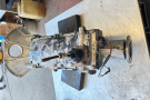
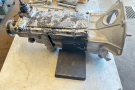
Now unbolt the carburettor and carefully lift it from the engine. The Holley unit must be placed on a stand before being put down as otherwise the throttle plates may be damaged. Holley manufactures its own stand assembly but an equally effective alternative is to use four 5/16ins bolts, one fitted into each of the carburettor flange bolt holes, with two nuts on each bolt to support the unit. Clean all traces of the old gasket from the manifold and the carburettor base flange using a soft scraper and then, before starting the work of dismantling the unit, clean all the grease and oil from the outside using paraffin (kerosene), a soft brush and clean, fluff-free cloth.
Gaskets and Repair Kits
Three types of gasket and repair kit are available from I Holley. These are a simple gasket set, a light repair kit and 2 Before starting to dismantle the carburettor, support it on a full repair kit, the latter containing almost every part of four 5/16ins bolts to avoid damaging the throttle plates the carburettor which can wear or break with the exception of the throttle shaft. The light repair kit is the one which is most often used and includes, in addition to all the gaskets you will require, all the parts which normally need replacement such as the jets, accelerator pump assembly and all rubber parts. Only if you have experienced a great deal of trouble from the particular carburettor fitted to your car will you need the full overhaul kit.
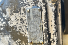
Remember when buying the repair kit that there are numerous minor variations between carburettors fitted to different cars, so you must quote the model number, which in this case will be 4150 or 4160 and the "list" number which is to be found on the outside casing of the air horn assembly and which specifically identifies your car's particular carburettor. With each repair kit you will find a comprehensive specification sheet which will give you all the necessary information for adjusting the carburettor when it is re-assembled and for this reason it is most important that you should insist on a genuine Holley kit because other kits which are also available, though containing the parts, may not include this vital information.
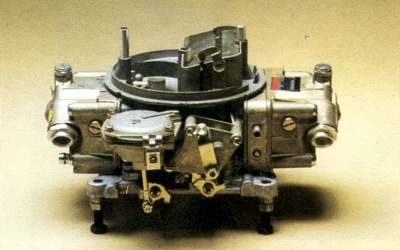
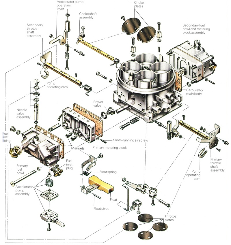
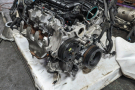
The Holley 4 barrel carby model 4160. Notice the carburettor shown is fitted with a manual choke.
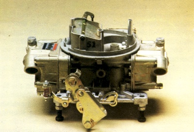
Before you start to dismantle the Holley carburettor, support it on 4 x 5/16th bolts to avoid damaging the throttle plates. |
Dismantling The Carburettor - Preliminary Steps
Start by removing the four screws that secure the secondary fuel bowl then lift off the fuel bowl, gasket and metering block in turn. It is possible that the assemblies will stick together in which case a tap with a soft-faced hammer or a screwdriver handle should part them. Some 4160 model carburettors have a metering plate instead of a metering block but the procedure for removing it is exactly the same. You may also find that your model has a single fuel inlet and a balance tube running between the two fuel bowls in which case you must pull off the "O" ring from the balance tube and fit a new one when re-building the unit. It is most important to fit this new "O" ring properly because fuel is fed under pressure through the tube and if you make any mistakes a fuel leak may result.
Now move to the opposite side of the carburettor and undo the four screws holding the primary side fuel bowl. The fuel bowl, rubber gasket and metering block are removed in exactly the same way as the secondary components taken off earlier. Place the components apart on a piece of clean paper because it is essential that they are replaced in their original positions. The choke unit may be either integral or remote, depending upon the requirements of the car manufacturer on whose vehicle the carburettor is fitted. If your car has an integral choke first pull out the small retaining pin from the bottom of the rod connecting the choke control unit to the choke lever, using a pair of long-nosed pliers.
Now look at the black plastic housing that contains the bi-metallic strip that operates the choke mechanism; you will see a mark on the housing itself and a series of similar marks on the choke casing. The two components must be re-assembled with the marks in the same relative positions so draw a diagram showing where the marks coincide. If you do find that you cannot remember how the two components were fitted when you come to put them back together you will have to refer to a Holley specification manual to discover the correct setting for your car's carburettor or speak to a helpful Holley retailer.
Remove the three screws securing the black, bi-metallic housing and carefully lift off the housing, gasket and retaining plate. Do not take the bi-metallic coil out of the housing. Next, remove the three screws which are now accessible and carefully lift off the metal choke housing from the main body of the carburettor itself. If your car has a remote choke assembly, undo and remove the two screws which retain the choke diaphragm and the screws securing the fast idle cam and lever retainer. If your particular model is fitted with a choke rod disconnect the retainer. Pull off the vacuum hose from the carburettor body and all of the choke components can then be lifted off.
Now move to the main diaphragm housing on the side of the carburettor body and carefully remove the circlip which retains the diaphragm lever. Proper circlip pliers are best for this but if you do not have any, long-nosed pliers should suffice. Once the circlip has been removed, undo the three screws which mount the diaphragm to the main body and lift off the assembly. Next, turn the carburettor upside down and undo the eight screws which attach the throttle body to the main body. These screws may be very difficult to turn and an impact screwdriver may be required to slacken them. Separate the throttle body from the main carburettor body making sure that the throttle plates are not damaged when the throttle assembly is put down.
Dismantling the Fuel Bowls
There will be slight differences in the fuel bowls, depending on whether the floats are pivoted at the front, the side or the back and whether the carburettor has a single or dual fuel inlet so bear this in mind when dismantling them. First remove the fuel inlet needle and seat. Loosen the lock screw and turn the hexagonal nut anti-clockwise until it is completely unscrewed from the needle and seat assembly, then lift out the needle. The float mounting bracket, upon which the float pivots, is secured by two screws which should now be removed. Once the screws are loosened, the float and bracket can be lifted out. If your fuel bowl has a side-mounted float, first remove the fuel baffle plate and then unclip the retainer from the float pin assembly, after which the float can be lifted out. The fuel inlet valve can be removed in the same way as front or rear-mounted float assemblies but if the valve is non-adjustable it must be unscrewed from inside the float-chamber using an open-ended spanner.
All Holley 4150 and 4160 carburettors have an accelerator pump assembly fitted in the primary side fuel bowl and on some models a similar pump is also fitted in the secondary bowl. Unscrew and remove the four retaining screws and lift off the assembly. Some accelerator pumps have a hanging ball inlet valve and you should check the clearance between the ball and its retainer. The parts will need replacing if the clearance falls outside the acceptable limits of 0.255 to 0.260 mm (0.011 to 0.013ins). Other models have a rubber umbrella inlet valve which should be taken out but which will not need to be replaced unless it shows visible signs of damage.
Dismantling the Metering Blocks
Start by removing the main metering jets using a screwdriver with a wide blade. It is most important that the screwdriver blade covers both sides of the slot because otherwise you will run the risk of damaging the jets. The jets in the primary and secondary metering blocks are often different sizes; if the carburettor has smaller primary venturi then the primary jets will probably be smaller. However, in some cases the jets will differ in size from side to side within the same metering block, so you must check the jet sizes and their locations and write these down before you consider removing any of them.
Now remove the bowl-vent splash shield together with any vacuum fittings that are fitted to your particular model, but on no account should you attempt to remove any pressed-in vacuum tubes. Unscrew both of the idle mixture screws from the primary metering block and carefully lift out the seals. To remove the power valves you will need a lins socket; you may be able to unscrew them using an open-ended spanner of the same size but you are more likely to cause damage if it slips. Unscrew the power valves and lift off the washers with them.
It should not be necessary to dismantle the metering blocks any further because the tubes inside the main and idling walls can be easily cleaned out using compressed air. On the model 4160 the secondary side consists only of a small metering plate and this cannot be dismantled any further. If the metering blocks on your model have an "O" ringed tube connecting them to the main carburettor body, remove the tube and discard the "O" rings. These will be replaced with those from the repair kit.
Dismantling the Choke Assembly
The integral choke assembly can be taken apart but before you do so have a good look at the components and the way in which they are fitted together so that you can re-assemble them correctly. Note especially the relationship between the fast idle cam and the choke operating lever. If you are at all unsure, it is best to take your time and draw a rough but reasonably accurate sketch of the unit. Unscrew the choke shaft nut and lift it off, together with its lock washer and spacers and then slide both the shaft and the fast idle cam from the housing assembly. Now carefully remove the choke qualifying piston but before you do so check that it operates freely in its bore because if it does not you will have to replace it. Finally, remove all traces of the old cork gasket surrounding the restriction on the rear of the choke housing completely. A new gasket from the service kit will be used on re-assembly. Unscrew and remove the four bolts securing the secondary diaphragm assembly and tap it gently with a screwdriver handle. This will separate the two halves and the spring and diaphragm can then be removed. Remove all of the old cork gasket using a suitable scraper.
Cleaning the Carburettor Parts
If you are planning to immerse all the parts in a special carburettor cleaning fluid then more dismantling will be necessary. If, however, you are going to use paraffin (kerosene) and a soft brush then this is as far as you need go. A great deal of extra work will be required if you use carburettor cleaning fluid and paraffin (kerosene) is a perfectly acceptable alternative so you will have to decide whether the extra effort is worthwhile. The work involved is as follows: from the main body file off the staked portion of the choke plate screws, then remove the screws and lift the choke plate out of the shaft. Now remove the choke shaft, the choke rod and the guide. Remove the pump discharge-nozzle screw, the nozzle and the gasket then turn the carburettor body over and remove the pump-discharging valve (some models have two pump-discharge assemblies).
Remember when you reassemble these components that the choke plate screws must be re-staked as if they come loose and drop into the engine a great deal of serious mechanical damage will be caused when the engine is started. Move to the throttle body and remove the idle-speed screw and spring, the diaphragm operating lever from the secondary throttle shaft and the fast idle lever from the primary shaft. Remove the cotter key and the connecting link between the primary and secondary throttle levers then file off the staked part of the throttle plate attachment screws, disconnect the plates, slide the shafts out of the flange and finally take out the "Teflon" bushes.
From the above it can be appreciated that unless you can see or have very good reason to believe that some component is actually damaged it is best to use paraffin (kerosene) and a soft brush rather than take on all this extra work just so that you can use the stronger carburettor cleaning fluid. Clean and dry every part separately and carefully inspect each component for any signs of undue wear. This way you will be able to see exactly which parts, if any, will need to be replaced. Remember that most parts which normally wear will be included in your repair kit, together with all gaskets so check in the kit before buying another part separately. Complete the cleaning process by blowing through all passages and restrictions with compressed air (a bicycle or car tyre pump is very useful for this) and remove any trace of the old gaskets from all the mating faces.
Re-Assembling the Carburettor
If you work slowly and methodically in the reverse of the dismantling procedure you should not encounter any problems when re-assembling the carburettor but remember that it is a very finely-tuned component and any wear or dirt will impair its correct functioning. So, before refitting any parts make quite certain that they are absolutely clean and show no signs of excessive wear. Make sure that all fixing screws are tight and that all of the gaskets are correctly replaced with new ones; it is possible, if you are not taking care, to overlook some of the smaller ones. It is necessary to make certain adjustments and checks during re-assembly and these are outlined below.
Checking the Dry Float Measurement
The level of fuel in the two float-chambers has to be maintained at a constant and pre-determined level; refer to the specification sheet included in your repair kit for the correct measurement for your particular carburettor. The sheet will also tell you where to make the measurement; this is usually between the bowl casing and the end of the float with the fuel bowl inverted but on some models this is not the case. If any adjustments are, in fact, necessary they can be made by carefully bending the tab until the correct reading is attained.
Checking the Choke Mechanism
It is vital, in order to ensure good starting and good fuel economy, that the choke assembly is properly adjusted. When re-assembling the mechanism first ensure that any marks made earlier coincide so that the relative positions of the individual components are unchanged. To check the choke-quality adjustment refer to the specification sheet for the correct figure for your model of carburettor and measure the clearance between the choke plate and the carburettor casting. The easiest way to take this measurement is to use the shank of a twist drill of the correct size. If any adjustments are necessary, bend the diaphragm link carefully to change its effective length.
When taking this measurement the choke plate must be held in the closed position, so you should carefully operate the diaphragm by hand. Now check the choke-unloader adjustment by holding the choke in a wide open position and measuring between the choke plate and the carburettor housing itself, again using a drill bit of the specified size. If the setting is incorrect, adjust the clearance by carefully bending the choke rod until the appropriate setting is obtained.
Adjusting the Accelerator Pump
Hold the throttle lever in the wide open position with the accelerator pump lever pressed down and measure the clearance between the spring adjuster nut and the arm of the pump lever. This clearance should be 0.38 mm (0.015ins) on all models and is adjusted by turning the nut or screw as required. The correct operation and adjustment of the accelerator pump is most important because when the throttle is opened suddenly the vacuum in the manifold drops sharply and fuel tends to condense on the manifold surfaces; in addition there is a lag in fuel delivery allowing more air to rush in, weakening the mixture. The accelerator pump counteracts this by discharging fuel directly into the venturi, thus acting as a mechanical injection system to supply the necessary fuel until the main jet begins its normal operation.
Setting the Adjustable Jets
Obviously, final adjustments to the jets cannot be made until the carburettor is re-installed on the engine and running at its normal operating temperature but you will find it extremely helpful to set them in approximately the correct position at this time. Start with the curb idle adjustment and turn the screw fully clockwise. Back off the screw one and a half turns and you will have a reasonable setting. The secondary idle speed adjustment is made in the same way but only back off this screw by one complete turn. Check the fast idle adjustment by setting the fast idle screw on the highest step of the fast idle cam and measuring between the primary throttle plate and the throttle bore; the clearance should be 0.6 mm (0.025ins) on most models but, as for all other adjustments, check the specification sheet for the precise figure for your car. Any necessary adjustments are made by bending the tang.
Re-Fitting The Carburettor
Use a new gasket and bolt the unit back on to the inlet manifold, tightening all the bolts by equal amounts so that the gasket is evenly compressed. If you marked all the hoses and cables which must now be re-connected you should not have any trouble identifying and replacing them in their original positions. Work all round the carburettor methodically making sure that nothing is left unconnected. Re-fit the air cleaner and start the engine, letting it reach its normal running temperature before making the final adjustments to the mixture and idling screws. When the work is completed you should notice a significant reduction in fuel consumption and an increase in the power and performance of your car's engine, all of which will more than repay you for the time taken.