The strength and the timing of the electrical spark that the distributor sends to the spark plugs directly affects the efficient running of a car's engine and if any part of the distributor is not functioning properly difficult starting, loss of power and an increase in fuel consumption will result. Adjustment and servicing should, therefore, be carried out at the intervals recommended by the manufacturers and not left until such time as the distributor actually begins to malfunction or stops working altogether.
Marelli distributors are fitted to several cars in the Fiat range except some
Fiat X1/9 models which have Ducellier units and some
Fiat 132 models which were fitted with a Bosch distributor. In addition, Marelli units may also be fitted to some Polski-Fiat, Lancia., Alfa Romeo and Autobianchi cars and some Porsche models. There are numerous minor variations between the different Marelli distributors but the servicing principles are similar.
The Function of the Distributor
The distributor is a complex component which must be capable of initiating up to at least 12,000 sparks per minute and then ensuring that they are directed to the right spark plug at the right time. First, in conjunction with the coil, the distributor initiates the high voltage (HT) current. Current from the primary windings in the coil runs to earth through the distributor contact breaker points and when the points are opened the circuit is broken and the current ceases to flow. This causes a collapse of the magnetic field around the coil core. As the lines of force which formed the field collapse they intersect with the secondary coil winding resulting in the creation of HT current which is then carried to the centre terminal of the distributor cap.
The second stage of the distributor's work is to "distribute" this HT current, in sequence, to the relevant spark plugs. The current is transferred from the centre terminal of the distributor cap, via a carbon brush, to the rotor arm which is attached to and driven by the distributor shaft. As the rotor arm passes each of the HT lead terminals inside the distributor cap, the HT current jumps the narrow gap and flows to the spark plug where it ignites the fuel and air mixture in the combustion chamber.

The older style Lucas 25D distributor with vacuum advance.
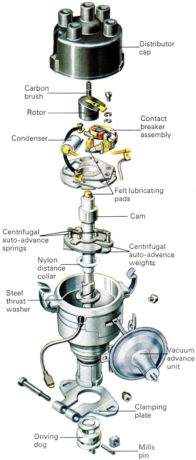
Lucas 45D distributor with one-piece contact breaker and non-adjustable vacuum advance unit. |
Servicing the Contact Breaker Assembly
The contact breaker assembly is the part of the distributor that requires the most frequent attention. The contact breaker points should normally be serviced every 10,000 km (6,000 miles). The service consists of checking the condition of the points faces and the adjustment of the gap between them. At 20,000 km (12,000 miles) the points and the condenser should both be renewed. Both items are usually available from accessory shops but in case of difficulty your local franchised dealer should be able to supply them.
Marelli makes two basic types of distributor. On the first type, which is more common, the contact breaker points are located beneath the centrifugal advance weights but it is still possible to check the points gap with the distributor fitted to the car. On the second type of distributor, fitted to Fiat 128 models for example, the points are mounted above the centrifugal advance weights. To gain access to the points, you must first remove the distributor cap. Label the spark plug leads with their respective cylinder numbers and pull the plug caps from the plugs. Disconnect the central HT lead from the distributor at the point where it is attached to the coil. Most Marelli distributor caps are secured by two screws and care should be exercised as you remove these as they can be easily dropped. A few models are fitted with the more universal spring clips which must be released. Lift off the cap complete with the HT leads (fig. 4).
It is possible to examine the condition of the contact breaker points while they are still attached to the distributor but as, at the very least, you will be cleaning the faces the job will be much easier if you remove the points assembly completely. To do this you will have to remove the rotor arm. Where the points are fitted below the weights, the rotor arm is attached to the weights by two screws. Undo these and lift the rotor arm away (fig. 6). Where the points are above the weights the rotor arm is a push-fit and can be removed by pulling it upwards or levering it gently with a screwdriver. Be careful not to damage any components if you have to use a screwdriver.
The points are a one-piece unit and can be removed from the first type of distributor after the locking screws on the base-plate have been undone. You may find it easier to disconnect the condenser lead by undoing its retaining screw and pushing the lead to one side. On the second type of unit, slacken the insulated terminal which is located on one side of the distributor body and slide out the contact breaker lead. Undo and remove the two screws which secure the contact points to the base-plate and lift the points assembly out.
With the points removed, hold the two faces apart so that you can examine their condition. If the faces are simply dirty they can be cleaned by rubbing them with a clean, petrol-soaked rag. If they are scaled they can be cleaned by using a fine-cut file but no attempt should be made to reshape the faces as it is impossible to achieve an exactly parallel finish. If one face is pitted and the other shows signs of a build-up in the form of a "pip", the points should be replaced. Do not be tempted to clean the points with sandpaper or emery cloth or this would score the faces and grind in dirt and result in premature wear. Re-fitting the points is a reversal of the removal procedure but if you are fitting a new set do not forget to clean the protective coating from the faces, using a clean rag dipped in petrol or paraffin (kerosene).
Adjusting the Points Gap
When you have assessed the condition of the points faces and taken the necessary steps to ensure that they are in good order, the points gap will have to be checked and, if necessary, adjusted carefully. With the points fitted to the distributor and with the cap and rotor arm still removed, turn the engine over until the rubbing block on the points is exactly on one of the peaks formed on the distributor shaft. In this position the points should be open. The amount by which the points open is known as the contact breaker gap. Refer to your handbook for the correct figure for your car and then insert a clean feeler gauge of the relevant thickness between the faces of the points. If the gap is too slack or if the faces are forced apart by the blade, you will have to re-set the adjustment.
On the first type of Marelli unit, where the points are below the weights, re-setting the gap is a little tricky. Slacken the two locking screws on the base-plate assembly using an open-ended 8 mm spanner. The position of the weights will prevent you from using a screwdriver for this job. With the screws loosened, move the points closer together or farther apart by inserting a screwdriver into the slot in the points set. If you loosen the screws just enough to permit the points to move very slightly you will be able to set the adjustment and check it with the feeler blade without running the risk of disturbing the setting as you re-tighten the screws.
When you are satisfied that you have achieved the correct setting and the points just nip the feeler blade, turn the engine so that another peak on the distributor shaft opens the points and re-check the gap. Make any necessary adjustments and then use the feeler to check the gap again. It is imperative that this job is done correctly so be patient until it has been achieved. With the second type of unit, slacken the two screws on the base-plate in the manner described and use a screwdriver to move the fixed contact until you achieve the required gap. The screws can then be re-tightened and the setting checked as described above.
Measuring the Dwell Angle
Measuring the points gap with a feeler gauge can be quite satisfactory but an even more accurate method of setting the adjustment is to use a dwell meter a number of which are available on the market which are suitable for the DIY user.
Checking the Distributor Cap and the Rotor Arm
While the distributor cap is removed, clean it thoroughly both inside and outside using a dry, fluff-free cloth. Check the cap carefully for any signs of cracks which could allow the current to escape to earth. If the cap is cracked this will lead to "tracking". This can be seen as a thin, wavy line of black carbon running from one of the terminals inside the cap where the current has been escaping to earth. If you suspect that your ignition system is tracking but cannot find any cracks examine the leads and the outside of the distributor cap in the dark and with the engine running. Tracking should show up as a series of blue sparks around the affected area. Any leads or the distributor cap should be replaced if tracking is evident.
Any light deposits on the terminals can be carefully scraped off with a small screwdriver. Heavy deposits, scoring or serious burning is unlikely but should you find any such condition renewal of the cap is, again, necessary. The carbon brush at the top of the cap should be in good condition and free to move up and down. Push it a few times to make sure that the spring is still functioning properly. Check also that the brush protrudes by at least 6 mm (jins). If there are any carbon deposits on the metal section of the rotor arm they should be cleaned away with white spirits or by rubbing it on the sidewall of a tyre.
Checking the Condenser
The function of the condenser is to prevent any sparking across the contact breaker points when they open, which would cause rapid burning and wear of the points. As it is wired in parallel with the contact breaker points any short-circuit in the condenser would result in a failure of the ignition system as the points would be prevented from interrupting the low-tension (LT) circuit. If the car tends to misfire after it has warmed up, if it is difficult to start or if the points can be seen to be extremely burned, then the condenser may be at fault.
Without expensive electronic equipment it is not possible to test the condenser other than by fitting a new one and seeing if there is any improvement in the vehicle's performance. To remove the condenser, remove the distributor cap, slacken the LT wire screw connection at the contact and remove the wire. The condenser is held in place by a single screw. Remove the screw and lift off the condenser. When re-fitting the condenser it is most important to ensure that both the LT lead and the condenser itself are tightly screwed down because if either is loose there is a danger of short-circuiting taking place.
Checking the Automatic Advance Springs
Without special test equipment there is no method of testing the springs on the centrifugal advance assembly. If you are in any doubt about their condition, all you can do is replace them. If the springs are loose where they link to the posts, it is very likely that the grooves on the posts are worn as well, which means that the distributor shaft will have to be replaced with a new one.
Removing the Distributor
It is quite possible to remove the distributor from the engine without upsetting the ignition timing, as long as you take certain precautions before you proceed. The first step is to turn the engine over until the timing marks are aligned and number one piston is at top dead centre (TDC) on the compression stroke. In the rare event that your car has no timing marks, refer to pages 97 to 102 for alternative methods of achieving the correct alignment. Next, remove the distributor cap and mark the location of the contact of the rotor arm in relation to the distributor body by scribing a line. Then scribe another line running from the distributor body to a point on the cylinder block. Disconnect the LT lead at the junction between the distributor and the coil. Use a screwdriver to lever apart the two plastic halves of the junction and then the spade terminal can be disconnected. The distributor is held in place by two bolts and one of them also retains a small plate which prevents the unit from rotating. Undo both bolts and lift out the distributor.
Dismantling and Overhauling the Distributor
With the distributor removed from the engine, clean away any oil or grease using paraffin (kerosene) and a soft paintbrush, then dry it thoroughly with a clean cloth. On units with the centrifugal advance weights fitted above the points, remove the rotor arm, contact breaker points and the condenser as described above. The next step is to knock out the pin which retains the lower collar or "oil thrower" on the distributor shaft. This L a tight friction fit and you will need a long, thin punch to remove it. Place the body of the distributor in a vice, using soft jaws to prevent damage to the unit. If soft vice jaws are not available, it is possible to clamp the unit between two blocks of wood or between two sheets of copper or brass. You can now drift out the pin.
With the pin removed, lift the rubber collar from the shaft but, as you do so, make a note of which way up it goes so that it can be replaced correctly. Between the oil thrower and the top of the shaft is a steel washer which should also be removed. Lift out the shaft complete with the centrifugal advance weights which will still be attached to it. All that secures the weights to the shaft are the two return springs fitted on top of the weights' assembly. Before removing the springs make a sketch of the way in which they are fitted as they must be replaced in exactly the same position. With the two springs removed you can now lift off the weights. The final step in the dismantling of the distributor is to separate the distributor shaft from the contact breaker plate. As nothing is now holding them together, the shaft can simply be pulled away from the plate.
On those distributors which have the centrifugal advance weights' assembly fitted in the main body of the unit with the points on top, the order of dismantling is different. First remove the rotor arm and points assembly as described above, then take out the insulated terminal from the side of the distributor body, making a careful note of how the insulators are fitted so that they can be correctly replaced. Undo and remove the screws which secure the base-plate and lift it out.
Use a screwdriver to lever out the felt wick in the top of the cam section of the distributor shaft and undo the screw underneath it. This will enable you to separate the cam section from the main part of the distributor shaft but before you do this use a small screwdriver to take off the centrifugal advance springs. Take care not to stretch them and make a sketch of the position of the bob weights to help you when you re-assemble the unit. As with other Marelli distributors, the main distributor shaft can be removed after the roll pin securing the retaining collar at the bottom of the shaft has been driven out. If the bearing bushes on either type of distributor need to be replaced the work is best carried out by your local dealer as he will have the necessary equipment to press the old ones out and the new ones into place.
Re-assembling the Distributor
Re-assembling the distributor is a reversal of the dismantling procedure but with either type make sure that the centrifugal advance weights and springs are thoroughly cleaned before you fit them to the contact breaker plate and the distributor shaft. Clean and lubricate the distributor shaft and its bushes before you fit it into place and always use a new roll pin to secure the collar at the bottom of the shaft. If LT leads appear to be chafed replace them. When re-building a distributor always fit a set of new contact breaker points and a new condenser to the unit.
Re-fitting the Distributor
Provided that the engine has not been turned over since you removed the distributor you can re-fit the unit by simply inserting it into the engine block. Make sure that all of the alignment marks match up and that the rotor arm is pointing to the same reference mark that you noted when removing the unit. As the helical gears on the drive engage it is likely that the rotor arm will be turned slightly out of alignment with the scribed marks. If this happens, withdraw the unit and turn the shaft slightly to make allowance for the gears engaging and then try again. This part of the job may take two or three attempts so be patient. When the marks are completely aligned secure the distributor by replacing and tightening the two retaining bolts. If the engine has been turned over with the distributor removed, align the timing marks so that number one piston is at TDC on the compression Stroke and then insert the distributor. Rotate it slightly until the contact breaker points just open, at which point the scribed marks should be in alignment. Tighten the two bolts.