Introduction
Engine-block design incorporating a separate cylinder-head has not always been the norm. Early engine designs were one-piece in construction. This was largely because engine technology was poor and components such as the valve-gear were primitive by today's standards. So it was easier for the block and head to be cast and machined as a single unit. But during the 1920s and 1930s engine design became much more complex. All production cars have the engine-block and head as two separate pieces, allowing for the head to be much more complex in design and to accommodate such features as overhead-valve operation.
Cylinder-Head Design
With most older car engines there are two main types of cylinder-head - those with overhead valves and push-rods and those which have overhead camshafts. Both types share many basic features, as each has to fulfil the same function of housing the combustion chamber, or at least (as in the case of bowl-in-piston arrangements, where the head is almost flat) being the roof of the chamber. Thus the head needs to contain all the components associated with combustion, such as the
cooling system, the manifolds and the valve gear.
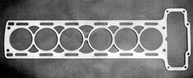
Cylinder-heads in petrol engines are all basically the same, regardless of the engine layout. For example, a V8 engine will have two heads each with only minor differences from the head on an in-line four. All cylinder-heads are made from either cast-iron or an alloy of aluminium. First they are cast in one piece and then the various passages, ports and flats are machined. The lower face of the cylinder-head is machined flat so that it mates well with the upper surface of the cylinder-block. Usually, however, the machining cannot be done accurately enough to provide the air-tight seal necessary to contain the gases of combustion, as well as the water in the cooling-jackets of water-cooled engines. So in order to make a good seal, a gasket is used between the head and block.
The head-gasket usually comprises a sandwich of copper and asbestos which is relatively soft. As the cylinder-head bolts are tightened down this gasket is compressed into all the imperfections in the head and block until a perfect seal is made. Because the gasket becomes compressed it can be used only once and must be replaced each time the cylinder-head is removed. Some designs of cylinder-head have the mating faces of the head and block machined to tighter tolerances than usual. But even these designs incorporate sealing washers around the waterways of the
cooling system. A 'blown' head-gasket or washer will result in the oil and petrol from the cylinders mixing with the water from the
cooling system (in a water-cooled engine), and some loss of compression. Such a situation may arise from a distortion of the head or block, usually caused by severe engine overheating, due in turn to a failure of the cooling or lubricating systems.
The Cooling System
As the cylinder-head contains, or is at least part of, the combustion-chamber, the head becomes extremely hot and needs as much cooling as the engine-block. Since they act as one unit, the head and block are cooled in the same way. Both are either water-cooled or
air-cooled. Water-cooled cylinder-heads have waterways cast into them which are continuations of the channels cast in the block. These are located around the whole head, but are larger or more numerous around such hot-spots as around the exhaust-valve guides. The heat generated in the cylinder-head is absorbed by the water circulating in the channels and passes out into the atmosphere as the water passes through the radiator.
Air-cooled cylinder-heads have fins cast on to them to match those on the block. These fins, by increasing the surface area of the head, offer a larger surface area to be cooled by the air. This process is usually accelerated by the operation of an engine-driven fan which blows air over the fins all the while that the engine is running.
The Manifolds
So that fuel vapour can enter the combustion-chamber and the spent gases leave it, the cylinder-head has to have inlet and exhaust channels to each cylinder machined in it. On the outside of the head, these channels are all linked by the manifolds. Flats and tapped holes are provided on the head for the attachment of the manifolds. The inlet manifold connects the carburettor to the head and thus the combustion-chamber, while the exhaust manifold carries the exhaust gases away from the head down to the silencer and pipe. Many automobile engines have the inlet and exhaust manifolds on the same side of the head, especially those vehicles with transversely mounted engines, where space is at a premium.
By having the two manifolds adjacent to each other, some of the heat from the exhaust gases is passed to the fuel vapour, warming it and assisting in its vaporization. The alternative design is the cross-flow cylinder-head which has the exhaust and inlet manifolds on opposite sides of the engine. While this arrangement requires an extra waterway under the carburettor to pre-heat the fuel vapour, it offers improved gas flow and increased engine efficiency.
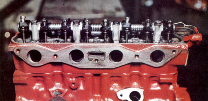
Two valve combustion chamber as found on the Ford Escort - the engine deisgn used a Heron head, thus the valves were vertical.
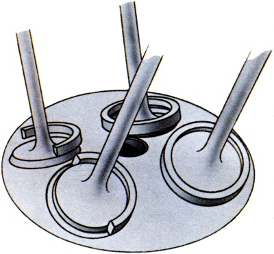
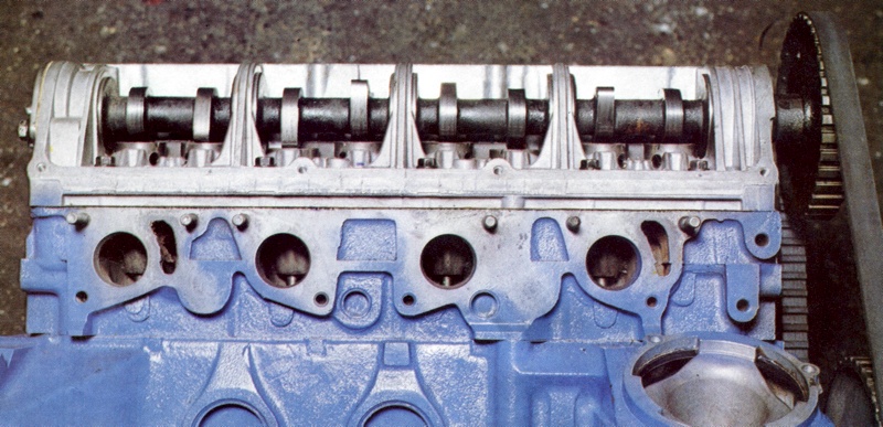
Four valve combustion chamber as found on the Triumph Dolomite- this design offered good engine breathing and better performance than the two valve design.
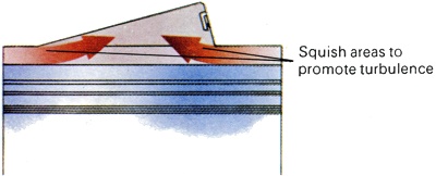
The combustion chamber has a significant squish area which promotes turbulence in the fuel vapour and helps direct its flow.
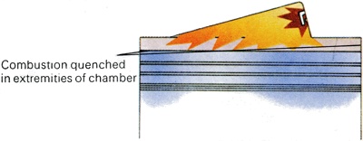
Squish areas may also act to quench combustion and so prevent the possibility of detonation in the extremities of the chamber.
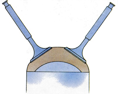
The hemispherical combustion chamber is the most efficient design. Its only drawback is the high cost of the angled valves.
The Heron Design alloed an almost flat head, but it overquenched combustion.
A wedge shaped combustion chamber with large squish and quench areas.
The bath-tub was a common design as vertical valves were much cheaper to manufacture. |
Valve Operation
One of the principal differences between cylinder-heads is the means of valve operation incorporated in them. There are two means by which the valves are operated. The most common means is through the use of push-rods and rockers and engines of this type are termed overhead-valve (OHV). A newer and more efficient method, used widely today, is through the direct action of an overhead-camshaft or camshafts, and these engines are called overhead-cam (OHC). The basic difference between the cylinder-heads of these two types is in the attachments and accommodation made for the valve-operating mechanisms.
The overhead-valve cylinder-head needs provision for the push-rods which operate the rocker shaft, and for the shaft itself. The overhead-cam type of head simply has to have anchorage points for the camshaft or camshafts. Double-overhead camshaft engines employ one shaft for the operation of the inlet valves and one for the exhaust valves. With either system, the shaft is housed at the top of the head under a cover usually called the rocker-box. Within this box, oil is sprayed or splashed through oil-paths or pipes in the head, so that the valve-operating shaft is kept well lubricated.
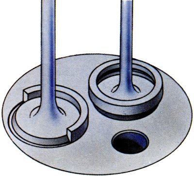
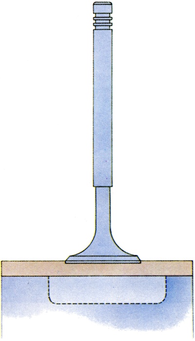
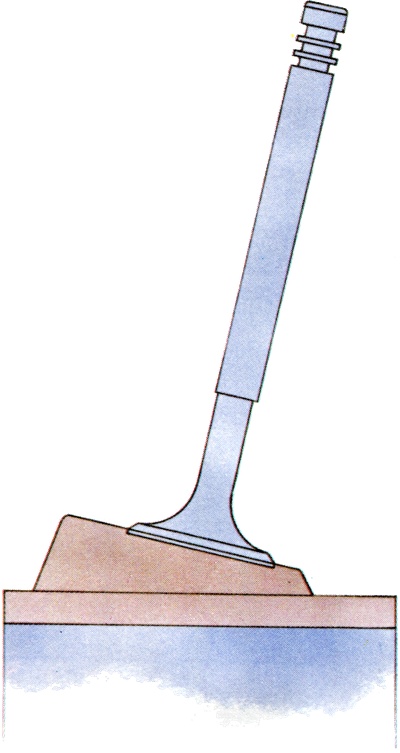
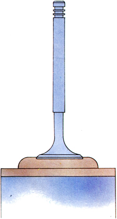
Whichever type of valve operation is used, the valves are basically the same and thus demand similar seats in all types of head. The vast majority of cylinder-heads have two valves per cylinder, one inlet and one exhaust. On some cars designed for high-performance, however, the engine breathing is improved by having four valves per cylinder (fig. 5), while others such as the Honda Civic have three valves per cylinder, two inlets and one exhaust.
As a rule, the ports for the inlet valves have to be larger, to accept a larger valve than the exhaust valve. This is because the induction of the fuel vapour is a much slower process than the expulsion of the exhaust gases. Induction relies on the suction caused by the piston moving down the cylinder, while the exhaust gases are forced out of the chamber as the piston rises up the bore.
Combustion-Chamber Design
The combustion-chamber is where the power of the engine is developed from the controlled burning of the fuel mixture. The form which the combustion-chamber takes has a crucial effect on the two most significant factors of the combustion process. These are the production of an even pressure on the piston through the even burning of the fuel, and the maintenance of a high combustion speed. A combustion-chamber in which the flame-path from the source of ignition, the spark-plug, would be even in all directions would need to be spherical, with the plug at its centre. As this is impossible some compromise has to be made. So the combustion-chamber is shaped to keep the flame-path as even as possible, and other means are also used to ensure that the fuel is burnt evenly and that the pressure on the piston is even.
A high combustion speed is produced and controlled by several factors. The first of these is turbulence in the fuel vapour, since if the gas is whirling about it will burn faster and more efficiently. Turbulence in the vapour is caused in several ways, the most effective being through 'squishing'. By designing the combustion-chamber so that the fuel/air mixture in part of it is compressed to a greater degree than elsewhere, a proportion of the vapour is squished at a high velocity into the remaining area. Not only does this promote faster burning but the direction of the burning can be predicted, as all the gas will be moving in roughly the same way.
Another important consideration in the design of the combustion-chamber is its volume-to-surface ratio. This is because of the need to maintain a high thermal efficiency �that is, the conservation of the heat produced by combustion for use in the combustion process itself. High temperatures can be maintained only if the volume of the chamber is high relative to its surface area. Again the ideal situation would be a spherical chamber, and again this is kept in mind when the inevitable compromises must be made. Where a head has a large surface area a lot of heat is lost, and this can actually lower the temperature of combustion enough to end it. This effect is called 'quenching'.
While a high temperature of combustion helps to provide a greater power output from the engine, there are limitations. For if the temperature and pressure rise beyond a certain point, the fuel vapour will explode instead of burning�that is, all the gas particles will ignite at once. This can have a disastrous effect on the engine, and pistons can be holed as a result. Detonation, or knocking as it is sometimes referred to, can be controlled in several ways. One way is to reduce the fuel's tendency to explode, this being done by the addition of lead compounds. Another way is to design a combustion-chamber in which the fuel is not squished and can nowhere become trapped and pressurized.
Some cylinder-heads allow for the possibility of detonation in their basic design, but also avoid it by quenching the last part of the combustion process where detonation might otherwise occur. In practice, there are four main types of combustion-chamber design. These are the hemispherical chamber, the wedge-shaped chamber, the bath-tub chamber and the bowl-in-piston chamber or Heron head. The Heron head which has the combustion-chamber almost entirely inside the piston, has an almost flat cylinder-head, simply incorporating the valves and spark-plug. The hemispherical chamber is probably the most efficient design. It approximates most closely the ideal, in that the flame-path is equal in all directions and the thermal efficiency high. However, it is generally used only on performance cars, because of the expensive angled location of its valves.
The most common designs used in production cars are the wedge and bath-tub chambers. These offer simpler valve arrangements than those in the hemispherical chamber, and so are cheaper to produce. Both these designs have significant squish areas to promote turbulence, but also require these areas to quench some of the fuel vapour to prevent the possibility of detonation which might occur in such irregular-shaped chambers. Part of the risk of detonation is removed, however, by the shortness of the flame-path from the spark-plug to the piston, thus limiting the turbulence.
The bowl-in-piston type of combustion-chamber has been a fairly recent experiment, the design being borrowed from diesel engines. This chamber allows a virtually flat cylinder-head to be used, with just a little depression in it to provide a squish area. The bowl-shaped combustion-chamber gives an even burning of the fuel vapour, but does tend to suffer from over-quenching, since the metal all around the chamber tends to dissipate the heat rapidly.
Pollution Control
While high-compression, fast-burning and non-knocking engines may be efficient and thus powerful, they do suffer from the fact that they produce a lot of pollution. Detonation of highly-compressed and fast burning fuel can be inhibited by adding lead�which is a pollutant�to the petrol, or by quenching part of the combustion process, which results in unburnt hydrocarbons being passed out into the air. In addition, the fact that the fuel vapour is burnt at a fast rate and high temperature also causes pollutants, in this case oxides of nitrogen, to be produced. With the governments of most nations having increased concern about pollution from the late 1960s onward, the engines cylinder-head/combustion-chamber designs were being judged on more than just their cheapness of manufacture or power output.
They had to meet emission-control regulations too. This was one reason why the Heron head, for example, was used less and less through the 1970s. Engine-block design incorporating a separate cylinder-head was not always the norm. Early engine designs were one-piece in construction. This was largely because engine technology was poor and components such as the valve-gear were primitive by today's standards. So it was easier for the block and head to be cast and machined as a single unit. Today's engines are much more complex. All production cars have the engine-block and head as two separate pieces, allowing for the head to be much more complex in design and to accommodate such features as overhead-valve operation.
Cylinder-Head Design
In current production cars there are two main types of cylinder-head - those with overhead valves and push-rods and those which have overhead camshafts. Both types share many basic features, for each has to fulfil the same function of housing the combustion chamber, or at least (as in the case of bowl-in-piston arrangements, where the head is almost flat) being the roof of the chamber. Thus the head needs to contain all the components associated with combustion, such as the
cooling system, the manifolds and the valve gear. Cylinder-heads in petrol engines are all basically the same, regardless of the engine layout. For example, a V-eight engine will have two heads each with only minor differences from the head on an in-line four.
All cylinder-heads are made from either cast-iron or an alloy of aluminium. First they are cast in one piece and then the various passages, ports and flats are machined. The lower face of the cylinder-head is machined flat so that it mates well with the upper surface of the cylinder-block. Usually, however, the machining cannot be done accurately enough to provide the air-tight seal necessary to contain the gases of combustion, as well as the water in the cooling-jackets of water-cooled engines. So in order to make a good seal, a gasket is used between the head and block. The head-gasket usually comprises a sandwich of copper and asbestos which is relatively soft. As the cylinder-head bolts are tightened down this gasket is compressed into all the imperfections in the head and block until a perfect seal is made.
Because the gasket becomes compressed it can be used only once and must be replaced each time the cylinder-head is removed. Some designs of cylinder-head have the mating faces of the head and block machined to tighter tolerances than usual. But even these designs incorporate sealing washers around the waterways of the
cooling system. A 'blown' head-gasket or washer will result in the oil and petrol from the cylinders mixing with the water from the
cooling system (in a water-cooled engine), and some loss of compression. Such a situation may arise from a distortion of the head or block, usually caused by severe engine overheating, due in turn to a failure of the cooling or lubricating systems.
The Cooling System
As the cylinder-head contains, or is at least part of, the combustion-chamber, the head becomes extremely hot and needs as much cooling as the engine-block. Since they act as one unit, the head and block are cooled in the same way. Both are either water-cooled or
air-cooled. Water-cooled cylinder-heads have waterways cast into them which are continuations of the channels cast in the block. These are located around the whole head, but are larger or more numerous around such hot-spots as around the exhaust-valve guides. The heat generated in the cylinder-head is absorbed by the water circulating in the channels and passes out into the atmosphere as the water passes through the radiator. Air-cooled cylinder-heads have fins cast on to them to match those on the block. These fins, by increasing the surface area of the head, offer a larger surface area to be cooled by the air. This process is usually accelerated by the operation of an engine-driven fan which blows air over the fins all the while that the engine is running.
The Manifolds
So that fuel vapour can enter the combustion-chamber and the spent gases leave it, the cylinder-head has to have inlet and exhaust channels to each cylinder machined in it. On the outside of the head, these channels are all linked by the manifolds. Flats and tapped holes are provided on the head for the attachment of the manifolds. The inlet manifold connects the carburettor to the head and thus the combustion-chamber, while the exhaust manifold carries the exhaust gases away from the head down to the silencer and pipe. Many automobile engines have the inlet and exhaust manifolds on the same side of the head, especially those vehicles with transversely mounted engines, where space is at a premium.
By having the two manifolds adjacent to each other, some of the heat from the exhaust gases is passed to the fuel vapour, warming it and assisting in its vaporization. The alternative design is the cross-flow cylinder-head which has the exhaust and inlet manifolds on opposite sides of the engine. While this arrangement requires an extra waterway under the carburettor to pre-heat the fuel vapour, it offers improved gas flow and increased engine efficiency.
Valve Operation
One of the principal differences between cylinder-heads is the means of valve operation incorporated in them. There are two means by which the valves are operated. The most common means is through the use of push-rods and rockers and engines of this type are termed overhead-valve (OHV). A newer and more efficient method, used widely today, is through the direct action of an overhead-camshaft or camshafts, and these engines are called overhead-cam (OHC). The basic difference between the cylinder-heads of these two types is in the attachments and accommodation made for the valve-operating mechanisms.
The overhead-valve cylinder-head needs provision for the push-rods which operate the rocker shaft, and for the shaft itself. The overhead-cam type of head simply has to have anchorage points for the camshaft or camshafts. Double-overhead camshaft engines employ one shaft for the operation of the inlet valves and one for the exhaust valves. With either system, the shaft is housed at the top of the head under a cover usually called the rocker-box. Within this box, oil is sprayed or splashed through oil-paths or pipes in the head, so that the valve-operating shaft is kept well lubricated.
Whichever type of valve operation is used, the valves are basically the same and thus demand similar seats in all types of head. The vast majority of cylinder-heads have two valves per cylinder, one inlet and one exhaust. On some cars designed for high-performance, however, the engine breathing is improved by having four valves per cylinder (fig. 5), while others such as the Honda Civic have three valves per cylinder, two inlets and one exhaust. As a rule, the ports for the inlet valves have to be larger, to accept a larger valve than the exhaust valve. This is because the induction of the fuel vapour is a much slower process than the expulsion of the exhaust gases. Induction relies on the suction caused by the piston moving down the cylinder, while the exhaust gases are forced out of the chamber as the piston rises up the bore.
Combustion-Chamber Design
The combustion-chamber is where the power of the engine is developed from the controlled burning of the fuel mixture. The form which the combustion-chamber takes has a crucial effect on the two most significant factors of the combustion process. These are the production of an even pressure on the piston through the even burning of the fuel, and the maintenance of a high combustion speed. A combustion-chamber in which the flame-path from the source of ignition, the spark-plug, would be even in all directions would need to be spherical, with the plug at its centre. As this is impossible some compromise has to be made. So the combustion-chamber is shaped to keep the flame-path as even as possible, and other means are also used to ensure that the fuel is burnt evenly and that the pressure on the piston is even.
A high combustion speed is produced and controlled by several factors. The first of these is turbulence in the fuel vapour, since if the gas is whirling about it will burn faster and more efficiently. Turbulence in the vapour is caused in several ways, the most effective being through 'squishing'. By designing the combustion-chamber so that the fuel/air mixture in part of it is compressed to a greater degree than elsewhere, a proportion of the vapour is squished at a high velocity into the remaining area. Not only does this promote faster burning but the direction of the burning can be predicted, as all the gas will be moving in roughly the same way.
Another important consideration in the design of the combustion-chamber is its volume-to-surface ratio. This is because of the need to maintain a high thermal efficiency - that is, the conservation of the heat produced by combustion for use in the combustion process itself. High temperatures can be maintained only if the volume of the chamber is high relative to its surface area. Again the ideal situation would be a spherical chamber, and again this is kept in mind when the inevitable compromises must be made. Where a head has a large surface area a lot of heat is lost, and this can actually lower the temperature of combustion enough to end it. This effect is called 'quenching'.
While a high temperature of combustion helps to provide a greater power output from the engine, there are limitations. For if the temperature and pressure rise beyond a certain point, the fuel vapour will explode instead of burning - that is, all the gas particles will ignite at once. This can have a disastrous effect on the engine, and pistons can be holed as a result. Detonation, or knocking as it is sometimes referred to, can be controlled in several ways. One way is to reduce the fuel's tendency to explode, this being done by the addition of lead compounds. Another way is to design a combustion-chamber in which the fuel is not squished and can nowhere become trapped and pressurized.
Some cylinder-heads allow for the possibility of detonation in their basic design, but also avoid it by quenching the last part of the combustion process where detonation might otherwise occur. In practice, there are four main types of combustion-chamber design. These are the hemispherical chamber, the wedge-shaped chamber, the bath-tub chamber and the bowl-in-piston chamber or Heron head. The Heron head which has the combustion-chamber almost entirely inside the piston, has an almost flat cylinder-head, simply incorporating the valves and spark-plug.
The hemispherical chamber is probably the most efficient design. It approximates most closely the ideal, in that the flame-path is equal in all directions and the thermal efficiency high. However, it is generally used only on performance cars, because of the expensive angled location of its valves. The most common designs used in production cars are the wedge and bath-tub chambers. These offer simpler valve arrangements than those in the hemispherical chamber, and so are cheaper to produce. Both these designs have significant squish areas to promote turbulence, but also require these areas to quench some of the fuel vapour to prevent the possibility of detonation which might occur in such irregular-shaped chambers. Part of the risk of detonation is removed, however, by the shortness of the flame-path from the spark-plug to the piston, thus limiting the turbulence.
The bowl-in-piston type of combustion-chamber has been a fairly recent experiment, the design being borrowed from diesel engines. This chamber allows a virtually flat cylinder-head to be used, with just a little depression in it to provide a squish area. The bowl-shaped combustion-chamber gives an even burning of the fuel vapour, but does tend to suffer from over-quenching, since the metal all around the chamber tends to dissipate the heat rapidly.
While high-compression, fast-burning and non-knocking engines may be efficient and thus powerful, they do suffer from the fact that they produce a lot of pollution. Detonation of highly-compressed and fast burning fuel used to be inhibited by adding lead - which is a pollutant - to the petrol, or by quenching part of the combustion process, which resulted in unburnt hydrocarbons being passed out into the air. In addition, the fact that the fuel vapour was burnt at a fast rate and high temperature also causes pollutants, in this case oxides of nitrogen, to be produced. It was the development of the cylinder-head/combustion-chamber design that went a long way to helping with the introduction of lead-free petrol.